Dr. Vadym Zayets
v.zayets(at)gmail.com
My Research and Inventions
click here to see all content |

Dr. Vadym Zayetsv.zayets(at)gmail.com |
|
 |
more Chapters on this topic:IntroductionTransport Eqs.Spin Proximity/ Spin InjectionSpin DetectionBoltzmann Eqs.Band currentScattering currentMean-free pathCurrent near InterfaceOrdinary Hall effectAnomalous Hall effect, AMR effectSpin-Orbit interactionSpin Hall effectNon-local Spin DetectionLandau -Lifshitz equationExchange interactionsp-d exchange interactionCoercive fieldPerpendicular magnetic anisotropy (PMA)Voltage- controlled magnetism (VCMA effect)All-metal transistorSpin-orbit torque (SO torque)What is a hole?spin polarizationCharge accumulationMgO-based MTJMagneto-opticsSpin vs Orbital momentWhat is the Spin?model comparisonQuestions & AnswersEB nanotechnologyReticle 11
more Chapters on this topic:IntroductionTransport Eqs.Spin Proximity/ Spin InjectionSpin DetectionBoltzmann Eqs.Band currentScattering currentMean-free pathCurrent near InterfaceOrdinary Hall effectAnomalous Hall effect, AMR effectSpin-Orbit interactionSpin Hall effectNon-local Spin DetectionLandau -Lifshitz equationExchange interactionsp-d exchange interactionCoercive fieldPerpendicular magnetic anisotropy (PMA)Voltage- controlled magnetism (VCMA effect)All-metal transistorSpin-orbit torque (SO torque)What is a hole?spin polarizationCharge accumulationMgO-based MTJMagneto-opticsSpin vs Orbital momentWhat is the Spin?model comparisonQuestions & AnswersEB nanotechnologyReticle 11
more Chapters on this topic:IntroductionTransport Eqs.Spin Proximity/ Spin InjectionSpin DetectionBoltzmann Eqs.Band currentScattering currentMean-free pathCurrent near InterfaceOrdinary Hall effectAnomalous Hall effect, AMR effectSpin-Orbit interactionSpin Hall effectNon-local Spin DetectionLandau -Lifshitz equationExchange interactionsp-d exchange interactionCoercive fieldPerpendicular magnetic anisotropy (PMA)Voltage- controlled magnetism (VCMA effect)All-metal transistorSpin-orbit torque (SO torque)What is a hole?spin polarizationCharge accumulationMgO-based MTJMagneto-opticsSpin vs Orbital momentWhat is the Spin?model comparisonQuestions & AnswersEB nanotechnologyReticle 11
more Chapters on this topic:IntroductionScatteringsSpin-polarized/ unpolarized electronsSpin statisticselectron gas in Magnetic FieldFerromagnetic metalsSpin TorqueSpin-Torque CurrentSpin-Transfer TorqueQuantum Nature of SpinQuestions & Answers
more Chapters on this topic:IntroductionTransport Eqs.Spin Proximity/ Spin InjectionSpin DetectionBoltzmann Eqs.Band currentScattering currentMean-free pathCurrent near InterfaceOrdinary Hall effectAnomalous Hall effect, AMR effectSpin-Orbit interactionSpin Hall effectNon-local Spin DetectionLandau -Lifshitz equationExchange interactionsp-d exchange interactionCoercive fieldPerpendicular magnetic anisotropy (PMA)Voltage- controlled magnetism (VCMA effect)All-metal transistorSpin-orbit torque (SO torque)What is a hole?spin polarizationCharge accumulationMgO-based MTJMagneto-opticsSpin vs Orbital momentWhat is the Spin?model comparisonQuestions & AnswersEB nanotechnologyReticle 11
more Chapters on this topic:IntroductionTransport Eqs.Spin Proximity/ Spin InjectionSpin DetectionBoltzmann Eqs.Band currentScattering currentMean-free pathCurrent near InterfaceOrdinary Hall effectAnomalous Hall effect, AMR effectSpin-Orbit interactionSpin Hall effectNon-local Spin DetectionLandau -Lifshitz equationExchange interactionsp-d exchange interactionCoercive fieldPerpendicular magnetic anisotropy (PMA)Voltage- controlled magnetism (VCMA effect)All-metal transistorSpin-orbit torque (SO torque)What is a hole?spin polarizationCharge accumulationMgO-based MTJMagneto-opticsSpin vs Orbital momentWhat is the Spin?model comparisonQuestions & AnswersEB nanotechnologyReticle 11
more Chapters on this topic:IntroductionTransport Eqs.Spin Proximity/ Spin InjectionSpin DetectionBoltzmann Eqs.Band currentScattering currentMean-free pathCurrent near InterfaceOrdinary Hall effectAnomalous Hall effect, AMR effectSpin-Orbit interactionSpin Hall effectNon-local Spin DetectionLandau -Lifshitz equationExchange interactionsp-d exchange interactionCoercive fieldPerpendicular magnetic anisotropy (PMA)Voltage- controlled magnetism (VCMA effect)All-metal transistorSpin-orbit torque (SO torque)What is a hole?spin polarizationCharge accumulationMgO-based MTJMagneto-opticsSpin vs Orbital momentWhat is the Spin?model comparisonQuestions & AnswersEB nanotechnologyReticle 11
|
Spin Proximity Effect. Spin Injection
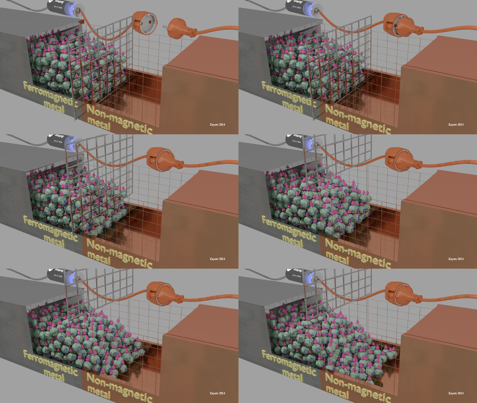
Spin and Charge Transport.In an equilibrium the electron gas is spin-polarized in a ferromagnetic metal and it is not spin-polarized in a non-magnetic metal . At a contact between a ferromagnetic and a non-magnetic metals, some spin accumulation from the ferromagnetic metal diffuses into the non-magnetic metal. The spin polarization in the ferromagnetic metal near the contact becomes smaller and the spin polarization in the non-magnetic metal becomes non-zero. This effect is called the Spin Proximity effect. This effect is called the Spin Proximity EffectWhen a drift current flows from a ferromagnetic to non-magnetic metal, the spin accumulation from the ferromagnetic metal may be drifted into the non-magnetic metal. This effect is called the Spin Injection The spin injection only modifies the distribution of the spin accumulation across the contact, which was initially established due to the Spin Proximity effect.
|
|
 |
| (classical incorrect view: Spin proximity effect) |
| (classical incorrect view: Spin injection effect) |
(exeption: intarfacial states as a gate)  In case of a tunnel junction the intefacial states prevents a free diffusion of spin through boundary between metals. In case the intrfacial states can be considered as a sort of a gate and spin diffusion becomes much more complex. (See details here) In case of a tunnel junction the intefacial states prevents a free diffusion of spin through boundary between metals. In case the intrfacial states can be considered as a sort of a gate and spin diffusion becomes much more complex. (See details here) |
1) Without an applied voltage, all spin accumulation contains only inside the ferromagnetic metal. It is like an invisible wall separates the ferromagnetic and non-magnetic metals from the spin diffusion.
2) When a voltage is applied, the wall is removed and the spin accumulation diffuses into the non-magnetic metal
Correct explanation of the Spin Injection and the Spin Proximity effects:
1) Even without an applied voltage the spin accumulation diffuses into the non-magnetic metal
2) The drift current only modifies the distribution of the spin accumulation across the contact:
(a) For one direction of current (the polarity of current depends on the metals), more spins are drifted from the from the ferromagnetic metal into the non-magnetic metal;
(b) For the opposite direction of the drift current, the spin accumulation is drifted back from the non-magnetic metal into the ferromagnetic metal.
When two metals, which have different spin polarization, are in contact, in the vicinity of the contact interface some spin-polarized electrons (electrons of TIA assembly) diffuse from the metal of a larger spin accumulation into the metal of a smaller spin polarization. For example, in the bulk of a non-magnetic metal the electron gas is not spin-polarized and it is spin-polarized in the bulk of a ferromagnetic metal. Near contact between ferromagnetic and non-magnetic metals the electron gas becomes spin-polarized in the non-magnetic material, because of the spin diffusion into this region from the neighboring region of the ferromagnetic metal. Correspondingly, the spin polarization in the ferromagnetic metal becomes smaller near the contact than in the bulk, because spins were diffused out of there.
Within the model of spin-up/spin-down bands it is assumed that in a contact between a ferromagnetic metal and a non-magnetic metal a spin accumulation is contained only inside the ferromagnetic metal and it does not diffuse into the non-magnetic metal (Fig.2 left). Only when a voltage is applied to the contact and a drift current flows through the contact, some of the spin accumulation may be drifted into the non-magnetic metal. This story contradicts with experimental observations . The presented model explains the spin injection and the spin transport through the contact differently. Even without a current nothing prevents a diffusion of a spin accumulation from the ferromagnetic metal into the non-magnetic metal. The spin accumulation decays from the ferromagnetic metal through the contact deep into the non-magnetic metal (Fig. 2 right). The drift current only modifies this distribution.
Contact between ferromagnetic and non-magnetic metals |
||||
|
Contact between ferromagnetic and non-magnetic metals |
||||
|
Spin polarization sp of electron gas in ferromagnetic nano-cylinder embedded in a non-magnetic metal |
||
|
||
Fig. 3. Calculated spin polarization of an electron gas in a ferromagnetic cylinder embedded in a non-magnetic metal. The diameter of the cylinder is 500 nm. The boundary of the cylinder is shown by the black circle. There is a significant spin diffusion from the ferromagnetic metal into the non-magnetic metal. Notice: more than 3 times reduction of the spin polarization in cylinder compared with the spin polarization of the bulk of the ferromagnetic metal Material Parameters (Click to expand) and Matlab/Comsol files. Do calculations by yourself !!!!!
Material parameters The spin polarization of the ferromagnetic metal: 0.6. The charge conductivity : 2E7 S/m (metal 1) ; 2E7 S/m (metal 2) . The density of the states at the Fermi level: 2E22 1/cm3/eV (metal 1) .2E22 1/cm3/eV (metal 2) The spin life time: 30 ps (metal 1); 30 ps (metal 2) The spin-diffusion conductivity : 2.6E7 S/m (metal 1) ; 2.6E7 S/m (metal 2) The injection conductivity: 1.4E7 S/m (metal 1) ; 1.4E7 S/m (metal 2) . The detection conductivity: 0 (metal 1) ; 0 (metal 2) Temperature is the room temperature. Data were calculated using the Finite Difference method. It was assumed that the conductivity near the interface is the same as the bulk conductivity and there is no contact conductivity. It is very rough assumption (See here).
Matlab/Comsol calculation filescalculate by yourself !!! CrookerMetal.m (Comsol only: CrookerMetal.mph )
|
Figure 3 shows the calculated distribution of spin polarization of an electron gas in a ferromagnetic cylinder embedded in a non-magnetic metal. The diameter of the cylinder is 0.5 um. The spin polarization is largest at the center of the cylinder and it becomes smaller at the edge. Even at the center of the ferromagnetic cylinder the largest spin polarization is about 0.13, which is significantly reduced from the bulk spin polarization of 0.6. Around the cylinder the electron gas in the non-magnetic metal is significantly spin-polarized. Therefore, the Spin Proximity effect causes the significant reduction of spin polarization of the electron gas in the ferromagnetic cylinder and it causes a spin polarization of the electron gas in the non-magnetic metal.
|
||
The Spin proximity effect at a contact between a ferromagnetic and a non-magnetic metals. Fig.3 The ratio of spin polarization at contact interface sp_interface to the equilibrium spin polarization sp0 of the ferromagnetic metal (left) as the function of the ration of the spin diffusion lengths in the metals. The conductivities of metals is the same; (right) as the function of the ration of the spin-diffusion conductivities. The spin is the same; |
Simplest case: 2D geometry; step-like conductivities
Inside of a non-magnetic metal the spin accumulation decays exponentially:

where lambda_non_mag is the spin diffusion length in the non-magnetic metal.
The spin polarization at the contact interface can be calculated as


From Eq. (3.2), the larger amount of spins, which diffuse from the ferromagnetic metal to the nonmagnetic metal, becomes larger when
(1) the conductivity of the non-magnetic metal decrease;
(2) the conductivity of the ferromagnetic metal increase;
(3) the spin diffusion length in the ferromagnetic metal decrease;
(4) the spin diffusion length in the non-magnetic metal increase;
Let us assume that a contact between a ferromagnetic and a non-magnetic metals at x=0
In the non-magnetic metal (x<0) the spin accumulation along the spin diffusion is described as

Corresponded the spin current in the non-magnetic metal is calculated as

In the ferromagnetic metal (x>0) the spin accumulation is described as

where sp0 is the equilibrium spin polarization in the ferromagnetic metal.
Corresponded the spin current in the ferromagnetic metal is calculated as

Through the interface, the spin polarization and the spin current are continuous without a steps. Theses boundary conditions give

or

From Eq.(3.15), the spin polarization at the contact interface is calculated as

 Calculate by yourself
Matlab file: ProximityMetal0.m
Comsol file: Proximity.mph

The Spin Proximity effect should be distinguished from the Magnetic Proximity effect (![]() 2014 Review is here). The Magnetic Proximity effect describes the change of magnetic properties of the localized d- or f- electrons in the vicinity of an interface, because of the interlayer exchange coupling. In contrast, the Spin Proximity effect describes the change of the spin polarization of the electron gas of the delocalized sp- electrons, because of the spin diffusion through the interface. Because of the sp-d exchange interaction between the localized and delocalized electrons, both effects are correlated. Still they can be distinguished, because of their different effective lengths. The effective length of the Magnetic Proximity effect and the interlayer exchange coupling does not exceed a few monolayers . In contrast, the effective length of the Spin Proximity effect is longer than several spin-diffusion lengths. Because of the different effective lengths, the Spin Proximity effect and the Magnetic Proximity effect can be distinguished experimentally .
2014 Review is here). The Magnetic Proximity effect describes the change of magnetic properties of the localized d- or f- electrons in the vicinity of an interface, because of the interlayer exchange coupling. In contrast, the Spin Proximity effect describes the change of the spin polarization of the electron gas of the delocalized sp- electrons, because of the spin diffusion through the interface. Because of the sp-d exchange interaction between the localized and delocalized electrons, both effects are correlated. Still they can be distinguished, because of their different effective lengths. The effective length of the Magnetic Proximity effect and the interlayer exchange coupling does not exceed a few monolayers . In contrast, the effective length of the Spin Proximity effect is longer than several spin-diffusion lengths. Because of the different effective lengths, the Spin Proximity effect and the Magnetic Proximity effect can be distinguished experimentally .
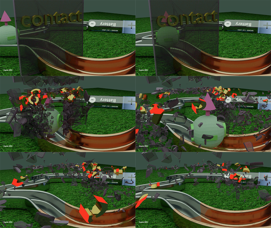
What is the spin injection??? Is it about the breaking of the spin through a contact between a ferromagnetic and a non-magnetic metals? Answer: It is not. It is a bulk effect. |
 |
Click on picture to enlarge it |
When a drift current flows through a contact between ferromagnetic and non-magnetic metals, an additional spin accumulation is drifted from the ferromagnetic metal into the non-magnetic metal. For the opposite direction of the current, the spin accumulation in the non-magnetic metal is drifted back into the ferromagnetic metal. This effect is called the spin injection. It is important to emphasize that the spin injection just changes the amount of spin accumulation in the non-magnetic metal, which already was there when there was no current.
 The spin injection only modifies the distribution of the spin accumulation across the contact, which was initially established due to the Spin Proximity effect.
It is important:
The spin injection by electron and holes currents are of opposite signs, because holes and electrons transport the spin in opposite directions (See bellow). In a semiconductor the current is either electron-type or hole-type. This is the reason why the spin injection is efficient in a semiconductor. In a metal there are both the electron and hole currents. This is the reason why the spin injection is not efficient in a metal.
|
||
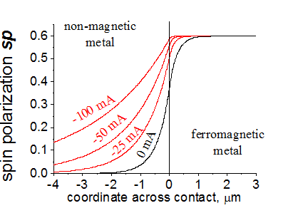
Fig.4. Spin polarization of the electron gas across the contact between a ferromagnetic and a non-magnetic metals for different values of charge current flowing through the contact. Even without the current (black line) there is a spin accumulation in the non-magnetic metal. For a negative current (red lines) the amount of the spin accumulation becomes larger. For a positive current (blue lines) the amount of the spin accumulation in the non-magnetic metal becomes smaller . The right picture is animated. The direction of the current is shown by the arrow. Comsol\Matlab calculation files are providedMaterial Parameters (Click to expand) and Matlab/Comsol calculation files. Do calculations by yourself !!!
Material parameters The contact area is 0.01 um^2. The spin polarization of the ferromagnetic metal: 0.6. The charge conductivity : 2E7 S/m (metal 1) ; 2E7 S/m (metal 2) . The density of the states at the Fermi level: 2E22 1/cm3/eV (metal 1) .2E22 1/cm3/eV (metal 2) The spin life time: 30 ps (metal 1); 30 ps (metal 2) The spin-diffusion conductivity : 2.6E7 S/m (metal 1) ; 2.6E7 S/m (metal 2) The injection conductivity: 1.4E7 S/m (metal 1) ; 1.4E7 S/m (metal 2) . The detection conductivity: 0 (metal 1) ; 0 (metal 2) Temperature is the room temperature. Data is calculated by solving numerically the Spin/Charge Transport Equations by Finite Difference Method (FDM) It was assumed that the conductivity near the interface is the same as the bulk conductivity and there is no contact conductivity. It is very rough assumption (See here). Matlab/Comsol calculation filesProximityMetal.m (comsol : ProximityMetal.mph)
|
Figure 4 shows the calculated distribution of the spin polarization across the contact between the ferromagnetic and the non-magnetic metals for different values of the drift current flowing across the contact. The constants of the metal are the same as were used for the calculations of Fig. 3. In all cases the spin polarization changes smoothly (without a step) from one metal to other metal. Even without a drift current, the electron gas is spin-polarized inside the non-magnetic metal and the spin polarization in the ferromagnetic metal is smaller than its bulk spin polarization. This is because of the Spin Proximity effect. For a negative drift current (red lines) the spin accumulation is drifted from the ferromagnetic metal into the non-magnetic metal. The spin polarization in the non-magnetic metal becomes larger and the spin polarization in the ferromagnetic metal becomes near 0.6, which is its bulk spin polarization. For a positive drift current (blue lines) the spin accumulation from the non-magnetic metal is drifted back into the ferromagnetic metal and most of the spin accumulation is depleted. In the ferromagnetic metal the spin accumulation is drifted deep inside of the bulk and near the contact interface the spin accumulation is depleted.
Material parameters
The contact area is 0.01 um^2.
The spin polarization of the ferromagnetic metal: 0.6.
The charge conductivity : 2E7 S/m (metal 1) ; 2E7 S/m (metal 2)
. The density of the states at the Fermi level: 2E22 1/cm3/eV (metal 1) .2E22 1/cm3/eV (metal 2)
The spin life time: 30 ps (metal 1); 30 ps (metal 2)
The spin-diffusion conductivity : 2.6E7 S/m (metal 1) ; 2.6E7 S/m (metal 2)
The injection conductivity: 1.4E7 S/m (metal 1) ; 1.4E7 S/m (metal 2)
. The detection conductivity: 0 (metal 1) ; 0 (metal 2)
Temperature is the room temperature.
Data is calculated by solving numerically the Spin/Charge Transport Equations by Finite Difference Method (FDM)
It was assumed that the conductivity near the interface is the same as the bulk conductivity and there is no contact conductivity. It is very rough assumption (See here).
ProximityMetal.m (comsol : ProximityMetal.mph)
 |
 |
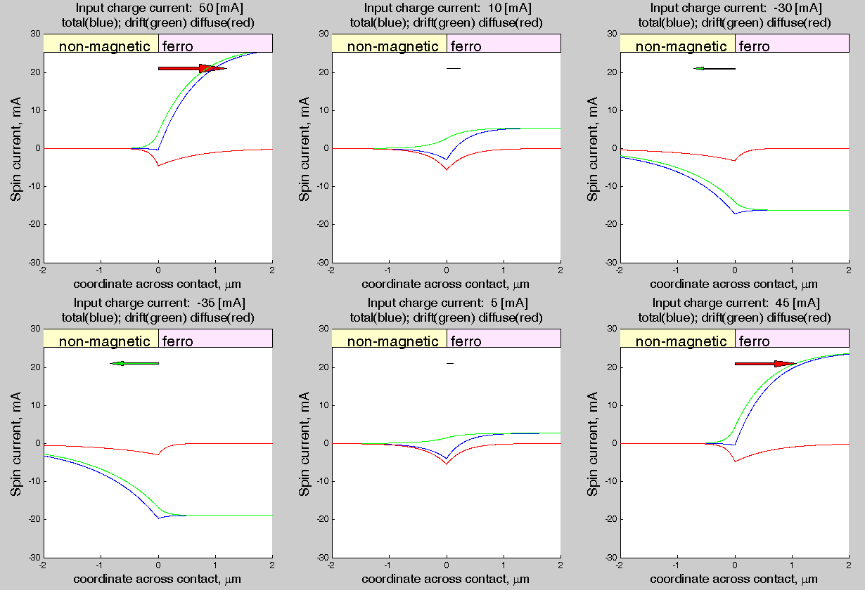 |
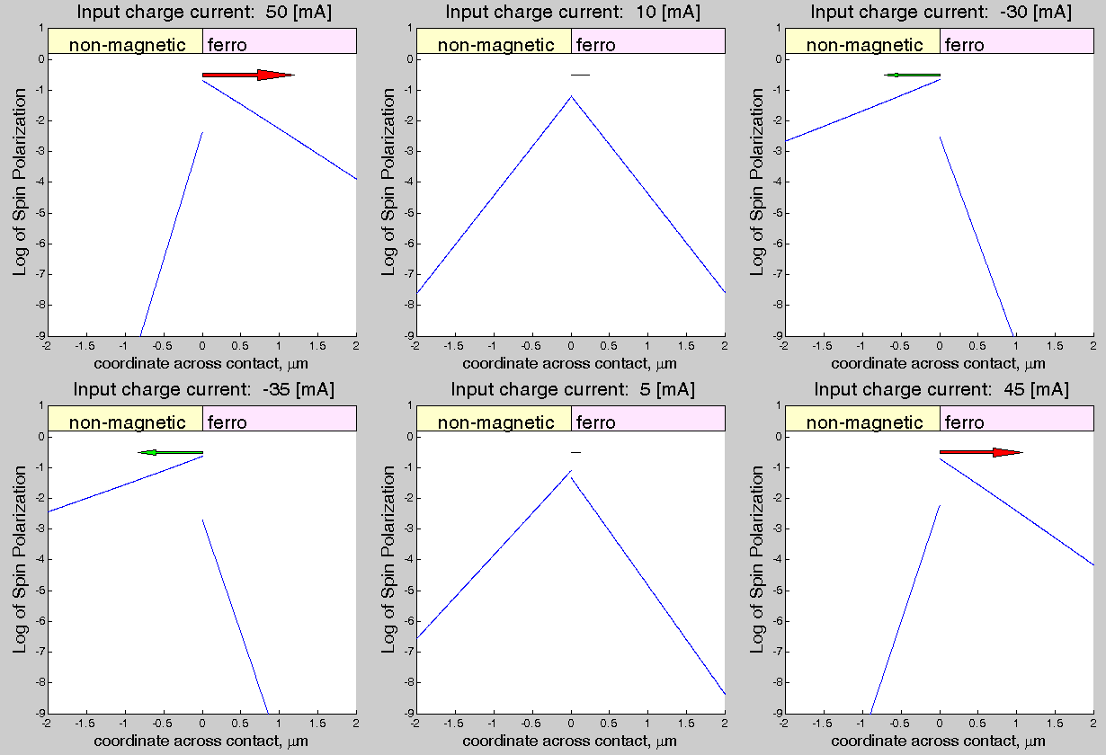
Fig. 4 (b). Log of the spin polarization in the vicinity of the contact between ferromagnetic and non-magnetic metals as the function of drift current flowing through the contact. The direction of the current is shown by the arrow. . The picture is animated. Comsol\Matlab calculation files are provided |
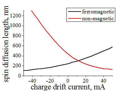
Fig. 4 (c) The effective spin diffusion length in the non-magnetic metal (black line) and ferromagnetic metal as the function of drift current flowing through the contact. Notice: spin diffusion length in non-magnetic metal without drift current is 464 nm |
Fig. 4(d). The total spin current (blue), drift spin current (green) and diffuse spin current (red) flowing through the contact between ferromagnetic and non-magnetic metals as the function of drift current flowing through the contact. The direction of the charge drift current is shown by the arrow. . The picture is animated. |
(fact) ![]() The spin diffusion length may be modulated substanially by the drift current (a conventional electron current) !!!
The spin diffusion length may be modulated substanially by the drift current (a conventional electron current) !!!
It is a bulk property of a conductor (but not contact property), when ![]()
In each metal the spin polarization decays exponentially (See Fig. (4(b)). Therefore, the distribution of the spin polarization in each metal can be fitted as
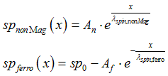
where x is the coordinate across the contact, sp0 is the bulk spin polarization of the ferromagnetic metals, An and Af are constants and![]() are the effective spin diffusion lengths in the non-magnetic and ferromagnetic metals, respectively.
are the effective spin diffusion lengths in the non-magnetic and ferromagnetic metals, respectively.
Figure 4(c) shows the effective spin diffusion length in the non-magnetic and ferromagnetic metals as the function of the drift current. When the spin accumulation is injected from the ferromagnetic to the non-magnetic metal (negative drift current), the effective spin length increases in the non-magnetic metal and it decreases in the ferromagnetic metal. This effect is called the spin gain/damping (See here) . It occurs because of the conversion of the spin drift current into the diffusion spin current along the flow of the drift current. When the flow of the converted spin current is in the same direction as the flow the diffusion current, the converted spin current assists the flow of the diffusion spin current and the spin diffusion length increases. When the direction is the opposite, the spin diffusion current is damped and the spin diffusion length decreases. The decrease and increase of the spin diffusion length depending of the direction of the spin current is well-confirmed and measured experimentally.

(1) The spin polarization sp monolithically (smoothly) changes through the interface between metals . The spin injection is the effect which occurs in the bulk of metals. The spin injection is not surface effect!!!
(2) The decay of spin accumulation into the bulk of metal is nearly exponential and it can be described by an effective diffusion length (Fig.4(c));
(3) The effective diffusion length in each metal depends on the current flowing through the contact (Fig.4(b)(c)). When the spin is injected into a non-magnetic metal, the effective spin diffusion length increase in the non-magnetic metal and decreases in the ferromagnetic metal. For opposite direction of current, the effective spin diffusion length increase in the the ferromagnetic metal and decreases in non-magnetic metal.
(4) Because of the Spin Proximity Effect, there is a diffusion spin current in both metals (Fig.4 (d)). The diffusion current is largest at the interface and its direction is from the ferromagnetic metal toward the non-magnetic metal. The diffusion spin current practically does not depend on the drift current.
(5) Distribution of spin accumulation in the vicinity of the contact practically does not change until the spin drift current becomes comparable with diffusion spin current.

It should be noticed that all above descriptions of the spin injection and the Spin Proximity effects were well-matched to experimental observations. For example, in this paper the spin injection from Fe into n-GaAs was studied and the spin accumulation in the GaAs was directly imaged using the Hanle effect. When the direction of the drift current is such that the electrons flow from the Fe into the n-GaAs, an increase of the spin accumulation in the n-GaAs is observed (Fig. 7(c), Fig.7 (e) of this paper) and the spin diffusion length is elongated in the n-GaAs. For the opposite direction of the current (Fig. 7(d), Fig.7 (f) of this paper), the spin accumulation in the n-GaAs decreases and the spin diffusion length is shortened.
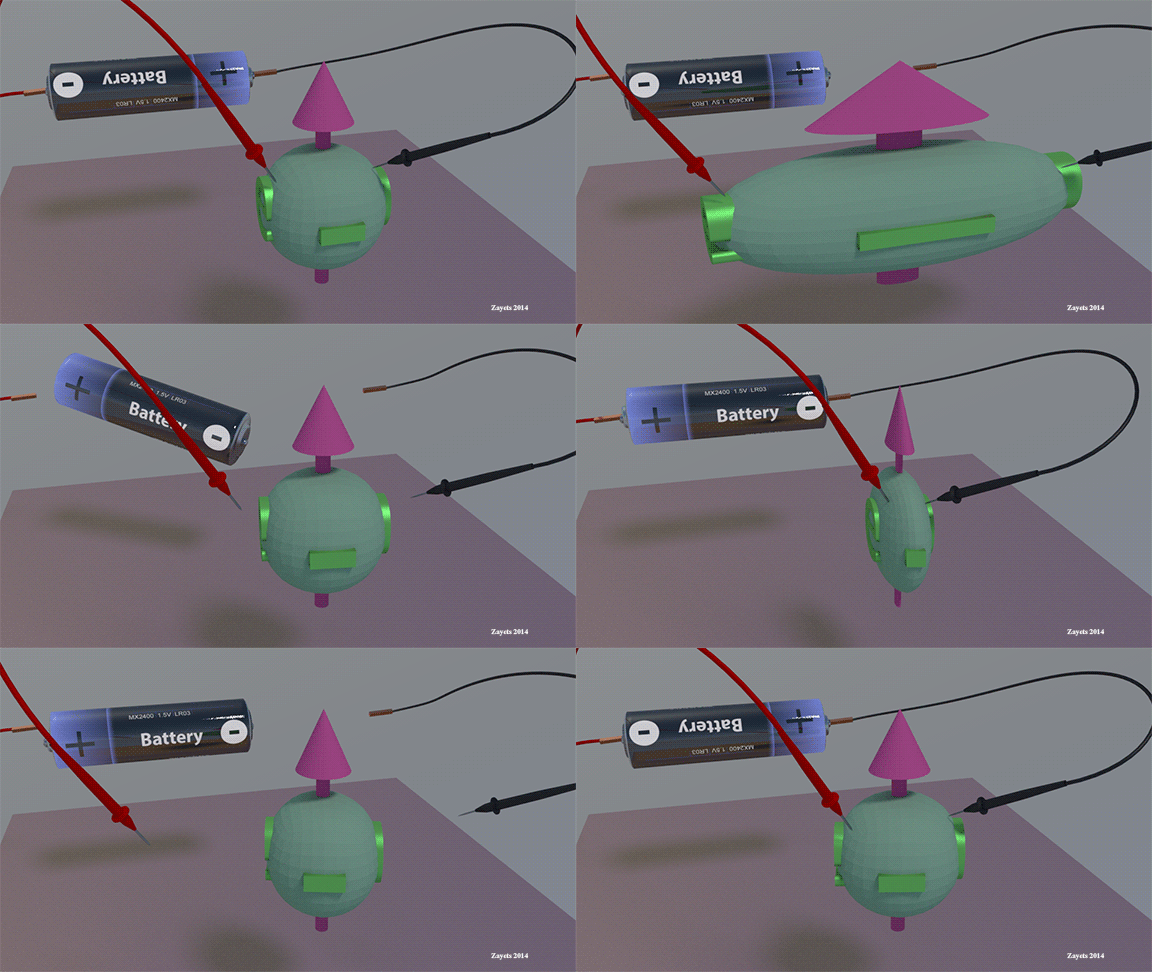
Spin diffusion length is either shorten or is elongated when an electrical current flows along the spin diffusion |
 |
Click on picture to enlarge it |
The shortening or the elongation of the spin diffusion length depends on the polarity of the battery with respect to the spin diffusion direction. Also, it depends on the sign of the injection conductivity |
in this case the detection conductivity is zero and the conductivities are constant with coordinates
In this case the effective spin diffusion length can be calculated as


where the spin diffusion length without a charge current is calculated as

where the threshold current of spin injection is

![]() ,
,![]() ,
, ![]() are the spin-diffusion, charge and injection conductivities, q is the electron charge, sp0 is the equilibrium spin polarization of the metal, tau_spin is the spin life time and n_spin is the number of the "spin" states in the metal
are the spin-diffusion, charge and injection conductivities, q is the electron charge, sp0 is the equilibrium spin polarization of the metal, tau_spin is the spin life time and n_spin is the number of the "spin" states in the metal
It should be noted that Eq. (20.1) is obtained ignoring the dependence of the number of the spin states n_spin on the spin polarization of the electron gas (See here). However, the variation of n_spin is only 10 % (See here) and Eq. (20.1) can be considered as a good approximation
In the case when conductivities are constant and ![]() =0, the spin/charge transport equations (See Eq.12) can be simplified as
=0, the spin/charge transport equations (See Eq.12) can be simplified as

The first equation is the Poisson equation. The second equation is simplified as

The charge current can be calculated as

Substitution of Eq.(20.6) in Eq.(20.5) gives

The solution of Eq. (20.7) can be found as

where![]() is the spin polarization at x=0;
is the spin polarization at x=0;
Substituting Eq. (20.8) , Eq. (20.7) is simplified as


or

where

Solving Eq. (20.11), the effective spin diffusion length is calculated as


When the current J_charge flows through the contact between a ferromagnetic metal and a non-magnetic metal, the spin polarization at contact interface can be calculated as

A spin current can be calculated as
The boundary condition of the continuous spin current through the contact interface gives

In the region of the ferromagnetic metal(x>0), the spin current can be calculated as

The boundary condition of the continuous spin current through the contact interface gives

Simplifying Eq.(30.4), we obtain

Solving Eq.(30.5), the spin polarization at contact interface sp(x=0) is obtained as


Dependence of spin injection efficiency on material parameters
Material parameters
The contact area is 0.01 um^2.
The spin polarization of the ferromagnetic metal: 0.6.
The charge conductivity : 2E7 S/m (metal 1) ; 2E7 S/m (metal 2)
. The density of the states at the Fermi level: 2E22 1/cm3/eV (metal 1) .2E22 1/cm3/eV (metal 2)
The spin life time: 30 ps (metal 1); 30 ps (metal 2)
The spin-diffusion conductivity : 2.6E7 S/m (metal 1) ; 2.6E7 S/m (metal 2)
The injection conductivity: 1.4E7 S/m (metal 1) ; 1.4E7 S/m (metal 2)
. The detection conductivity: 0 (metal 1) ; 0 (metal 2)
Temperature is the room temperature.
Data is calculated by solving numerically the Spin/Charge Transport Equations by Finite Difference Method (FDM)
It was assumed that the conductivity near the interface is the same as the bulk conductivity and there is no contact conductivity. It is very rough assumption (See here).
All data below are calculated by solving numerically the Spin/Charge transport equations


The spin injection efficiency is characterized by the change of the efficient spin diffusion length ![]() in the non-magnetic and ferromagnetic metals and the change of the spin polarization at the contact interface
in the non-magnetic and ferromagnetic metals and the change of the spin polarization at the contact interface ![]()
Spin injection into the bulk of a non-magnetic metal |
Spin depletion from the bulk of a non-magnetic metal |
 |
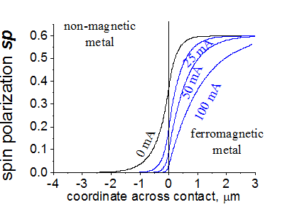 |
Fig.11 The spin injection into the bulk of a non-magnetic metal. It occurs when (a) (b) Material parameters is the same as for Fig.4 above. |
Fig.12. Spin depletion from the bulk of a non-magnetic metal. It occurs when when (a) (b) |
Case 1. Injection conductivity is electron-dominated for both the ferromagnetic and the non-magnetic metals.
![]() <0;
<0; ![]() <0
<0
Polarity: "-" to the ferromagnetic metal; "+" to the non-magnetic metal (spin injection)
![]() increases in the non-magnetic and it decreases in the ferromagnetic metal.
increases in the non-magnetic and it decreases in the ferromagnetic metal. ![]() increases.
increases.
The amount of spin-polarized carriers in the non-magnetic metal increases. It is always smaller than the equilibrium spin polarization of the ferromagnetic metal sp0.
Polarity: "+" to the ferromagnetic metal; "-" to the non-magnetic metal (spin depletion)
![]() decreases in the non-magnetic and it increases in the ferromagnetic metal.
decreases in the non-magnetic and it increases in the ferromagnetic metal. ![]() decreases.
decreases.
The amount of spin-polarized carriers in the non-magnetic metal decreases.
-------------------------------------------------------------------------
Case 2. Injection conductivity is hole-dominated for both the ferromagnetic and the non-magnetic metals.
![]() >0;
>0; ![]() >0
>0
Polarity: "+" to the ferromagnetic metal; "-" to the non-magnetic metal (spin injection)
![]() increases in the non-magnetic and it decreases in the ferromagnetic metal.
increases in the non-magnetic and it decreases in the ferromagnetic metal. ![]() increases. It is always smaller than the equilibrium spin polarization of the ferromagnetic metal sp0.
increases. It is always smaller than the equilibrium spin polarization of the ferromagnetic metal sp0.
The amount of spin-polarized carriers in the non-magnetic metal increases.
Polarity: "-" to the ferromagnetic metal; "+" to the non-magnetic metal (spin depletion)
![]() decreases in the non-magnetic and it increases in the ferromagnetic metal.
decreases in the non-magnetic and it increases in the ferromagnetic metal. ![]() decreases.
decreases.
The amount of spin-polarized carriers in the non-magnetic metal decreases.
Spin injection into the interface |
Spin depletion from the interface |
 |
 |
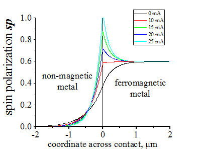
Fig.11 The spin injection into the interface. There is a significant increase of the spin polarization at the interface when a charge current flows through the interface. Even though the spin polarization in the non-magnetic metal decreases It occurs when (a) (b) Material parameters is the same as for Fig.4 above. |
Fig.12. Spin depletion from the interface. The spin polarization decreases when a charge current flows through the interface. Even though the spin polarization in the non-magnetic metal increases It occurs when when (a) (b) |
----------------------------------------------------------------------------
Case 3. Injection conductivity is hole-dominated in the ferromagnetic metal and electron-dominated in the non-magnetic metals.
![]() >0;
>0; ![]() <0
<0
Polarity: "+" to the ferromagnetic metal; "-" to the non-magnetic metal (spin accumulation at interface)
![]() decreases in both the non-magnetic and in the ferromagnetic metal.
decreases in both the non-magnetic and in the ferromagnetic metal.
In the ferromagnetic metal, ![]() may change its sign.
may change its sign.
![]() increases. It can be larger even than the equilibrium spin polarization of the ferromagnetic metal sp0
increases. It can be larger even than the equilibrium spin polarization of the ferromagnetic metal sp0
Polarity: "-" to the ferromagnetic metal; "+" to the non-magnetic metal (spin depletion)
![]() increases in both the non-magnetic and in the ferromagnetic metal.
increases in both the non-magnetic and in the ferromagnetic metal.
![]() is nearly a constant. (With increasing current, in increases or decreases. and next it is saturated at constant value)
is nearly a constant. (With increasing current, in increases or decreases. and next it is saturated at constant value)
When the spin life time in the metal decrease,
its spin length![]() decreases, which causes decreasing
decreases, which causes decreasing
Animated parameter: Spin life time in ferromagnetic metal |
||||
|
Animated parameter: Spin life time in non-magnetic metal |
||||
|
Animated parameter: Conductivity of non-magnetic metal.note: Density of states is constant |
||||
|
t
The spin injection may occur not only between two metals, but within the same metal as well. Figure 6 shows the calculated spin polarization induced in the non-magnetic metal by circularly-polarized light at different voltages applied in the plane of the metal. When a voltage is not applied in-plane of the metal, the distribution of the spin polarization is Gaussian. When the voltage is applied, the spin polarization is drifted along the voltage. The drift only occurs in metals in which ![]() . The drift of the spin polarization similar to that calculated in Fig.6 was observed experimentally in n-GaAs (Fig.4 of this paper).
. The drift of the spin polarization similar to that calculated in Fig.6 was observed experimentally in n-GaAs (Fig.4 of this paper).
The spin injection within a single material. Drift of spin accumulation, which is excited by a laser beam. |
||
|
||
Fig.6. The drift of the spin polarization in a metal under an applied electrical field. The spin polarization of metal is induced by circularly polarized light. The light beam is Gaussian. The beam diameter is shown by the black circle. Comsol\Matlab calculation files are providedMaterial Parameters (Click to expand) and Matlab/Comsol calculation files. Calculate by yourself !!!
Material parameters The spin polarization of the ferromagnetic metal: 0.6. The charge conductivity : 2E7 S/m . The density of the states at the Fermi level: 2E22 1/cm3/eV The spin life time: 30 ps The spin-diffusion conductivity : 2.6E7 S/m The injection conductivity: 1.8E7 S/m (metal 1) . The detection conductivity: 0 (metal 1) Temperature is the room temperature. Data were calculated using the Finite Difference method.
Matlab/Comsol calculation filescalculate by yourself !!! CrookerMetal.m (Comsol only: CrookerMetal.mph )
|
The spin injection within a single material.Drift of spin accumulation, which is excited by a laser beam. |
||||||||
|
Classical model assumes that without a drift current there is no spin accumulation in a non-magnetic metal at a contact with a ferromagnetic metal. All spin accumulation contains within the ferromagnetic metal. Step-like contact between the metals is considered as a wall for any spin diffusion into ferromagnetic metal. A drift current drugs some spin accumulation through the interface between metals into the non-magnetic metal. As the spin accumulation has passed the contact, it diffuses in the non-magnetic. This interpretation of the spin injection is incorrect.
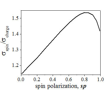 |
| The ratio of the spin-diffusion conductivity to the charge (conventional) conductivity in a metal |
The spin-diffusion conductivity ![]() describes the conventional spin diffusion along a gradient of the spin polarization.
describes the conventional spin diffusion along a gradient of the spin polarization.
![]() is large in both the metals and the semiconductors
is large in both the metals and the semiconductors
In the case of a semiconductor, ![]() equals to the conventional conductivity
equals to the conventional conductivity![]() .
.
In the case of a metal, ![]() is larger than the conventional conductivity
is larger than the conventional conductivity![]() (See here) and it depends on the spin polarization of the electron gas .
(See here) and it depends on the spin polarization of the electron gas .
 |
| The value of |
The injection conductivity![]() defines a ratio of how much the spin polarization of the drift current smaller than the spin polarization of the electron gas. It describes the ability of a drift current to transport a spin accumulation.
defines a ratio of how much the spin polarization of the drift current smaller than the spin polarization of the electron gas. It describes the ability of a drift current to transport a spin accumulation.
![]() is small in a metal and it is large in a semiconductor
is small in a metal and it is large in a semiconductor
In the case of a semiconductor, ![]() equals to the conventional conductivity
equals to the conventional conductivity![]() .
.
In the case of a metal, ![]() is small and it is only 1-10% of the conventional conductivity
is small and it is only 1-10% of the conventional conductivity![]() . It is because the directions of spin transfer is opposite for the electron and hole currents in the metal.
. It is because the directions of spin transfer is opposite for the electron and hole currents in the metal.
 Why spin injection conductivity is small in a metal and it is large in a semiconductor?
In metals-> spin injection efficiency is weak In semiconductors-> spin injection efficiency is large |
 |
Reason: In metals,the spin electron and hole drift currents are opposite and they are about the same. In total , the spin drift current is small. In a semiconductor current is either electron-type or hole-type |
The spin polarization of a spin current in a semiconductor is almost equal to the spin polarization of the electron gas. In contrast, in a metal the spin polarization of a spin current is significantly smaller than the spin polarization of the electron gas. This fact is proved here from a solution of the Boltzmann transport equations. A simplified explanation of this fact can be given as follows. In an n-type semiconductor the charge and spin are transported by electrons. The negatively-charged electrons move from a “-“source towards a “+” drain and the spin is drifted in the same direction. In a p-type semiconductors the charge and spin are transported by holes. The positively-charged holes move from a “+“ towards a “-” drifting the spin in the same direction. Therefore, the spin drifting direction is opposite in the n-type and p-type semiconductors. This is the reason of the opposite signs of for n- and p- semiconductors. The electrical conduction in a metal can be seen as a drift of electrons and hole in opposite directions (Fig.7). Since the charge of electrons and holes is opposite, the electron and hole currents transport the charge in the same direction, but they transport the spin in opposite directions. Since the number of electrons and holes is about the same in a metal, the spin drifting by electrons and holes nearly compensate each other. This causes a small spin-polarization of a drift current in a metal and a small value of . The sign of in a metal may be either negative or positive depending on whether there are more electrons or holes in the metal. The later condition is determined by the sign of the gradient of the density of the states of the metal at the Fermi energy. The sign of is important for an effective spin injection. For example, for an effective spin injection from a ferromagnetic metal to a non-magnetic metal, the sign of should be the same for the ferromagnetic and non-magnetic metals. The polarity of the applied voltage should correspond to the sign of ![]() . The sign of
. The sign of ![]() can be evaluated from the sign of the Hall voltage in the metal .
can be evaluated from the sign of the Hall voltage in the metal .
|
||
Fig. 7 The negatively-charged electrons (green balls) moves from "-" to "+". The positively-charged holes (blue balls) moves from "+" to "-". Therefore, the electron and hole currents transform the charge in the same direction, but the spin in opposite direction. Since in a metal about the same number of holes and electrons, the spin-transfer efficiency (spin-injection efficiency) is small in a metal. |
It is important:
An efficient spin injection is important for a variety of different application. For example, the largest spin-transfer torque is one of main required parameters for a cell of magnetic random-access memory (MRAM). The largest spin-transfer torque is only possible in the case when there is an efficient spin injection between the electrodes of the MRAM cell (See here) . It is possible only when metals with the largest value of ![]() are used as electrodes of the MRAM cell.
are used as electrodes of the MRAM cell.

The effect of the spin transfer torque occurs because of the spin injection from one electrode of a MTJ to another electrode. For largest spin transfer torque, metals with largest injection conductivity ![]() are preferable as a material for electrodes
are preferable as a material for electrodes
What is the spin injection??? Is it about the breaking of the spin through a contact between a ferromagnetic and a non-magnetic metals? Answer: It is not. It is a bulk effect. |
 |
Click on picture to enlarge it |

Q. Is this the breaking of the spin throughout a contact between a ferromagnetic and a non-magnetic metal???
A. It is not!! It is a bulk effect
Q. Is the amount of the spin accumulation, which is drifted through the contact, linearly proportional to the drift current?
A. It is only in the case of current larger than the the threshold injection current J0.
Q. What the spin injection do???
A. The spin injection is:
a) The change of spin diffusion length due to the drift current. The change occurs in the bulk of a metal.
b) The change of the amount of the spin accumulation at the contact interface between two metals, because of the change of the spin diffusion length in each metal. (see Fig. 3)
Experimental proof of spin proximity effect
Shape of hysteresis loop for Anomalous Hall effect. Experiment
|
||||||
|
![]() Possible confusion!!: from 2014 to 2017 I have used names TIA and TIS for groups of spin-polarized and spin-unpolarized electrons, respectively. The reasons are explained here.
Possible confusion!!: from 2014 to 2017 I have used names TIA and TIS for groups of spin-polarized and spin-unpolarized electrons, respectively. The reasons are explained here.
I will try to answer your questions as soon as possible