Dr. Vadym Zayets
v.zayets(at)gmail.com
My Research and Inventions
click here to see all content |

Dr. Vadym Zayetsv.zayets(at)gmail.com |
|
|
classic model ofspin transportmodel of spin-down/spin-up bandsmore chapters on this topic:IntroductionBasic Transport equationsSpin and charge currentsSpin drainNon-magnetic metalsFerromagnetic metalsSemiconductors (Basic)Threshold spin currentSpin gain/dampingSpin RelaxationSpin Hall/ Inverse Spin Hall effectsee-interaction
classic model ofspin transportmodel of spin-down/spin-up bandsmore chapters on this topic:IntroductionBasic Transport equationsSpin and charge currentsSpin drainNon-magnetic metalsFerromagnetic metalsSemiconductors (Basic)Threshold spin currentSpin gain/dampingSpin RelaxationSpin Hall/ Inverse Spin Hall effectsee-interaction
classic model ofspin transportmodel of spin-down/spin-up bandsmore chapters on this topic:IntroductionBasic Transport equationsSpin and charge currentsSpin drainNon-magnetic metalsFerromagnetic metalsSemiconductors (Basic)Threshold spin currentSpin gain/dampingSpin RelaxationSpin Hall/ Inverse Spin Hall effectsee-interaction
classic model ofspin transportmodel of spin-down/spin-up bandsmore chapters on this topic:IntroductionBasic Transport equationsSpin and charge currentsSpin drainNon-magnetic metalsFerromagnetic metalsSemiconductors (Basic)Threshold spin currentSpin gain/dampingSpin RelaxationSpin Hall/ Inverse Spin Hall effectsee-interaction
classic model ofspin transportmodel of spin-down/spin-up bandsmore chapters on this topic:IntroductionBasic Transport equationsSpin and charge currentsSpin drainNon-magnetic metalsFerromagnetic metalsSemiconductors (Basic)Threshold spin currentSpin gain/dampingSpin RelaxationSpin Hall/ Inverse Spin Hall effectsee-interaction
classic model ofspin transportmodel of spin-down/spin-up bandsmore chapters on this topic:IntroductionBasic Transport equationsSpin and charge currentsSpin drainNon-magnetic metalsFerromagnetic metalsSemiconductors (Basic)Threshold spin currentSpin gain/dampingSpin RelaxationSpin Hall/ Inverse Spin Hall effectsee-interaction
classic model ofspin transportmodel of spin-down/spin-up bandsmore chapters on this topic:IntroductionBasic Transport equationsSpin and charge currentsSpin drainNon-magnetic metalsFerromagnetic metalsSemiconductors (Basic)Threshold spin currentSpin gain/dampingSpin RelaxationSpin Hall/ Inverse Spin Hall effectsee-interaction |
Spin and Charge Transport in Semiconductors Spin and Charge Transport. Classical model of the spin-up/spin-down band.
|
|
||
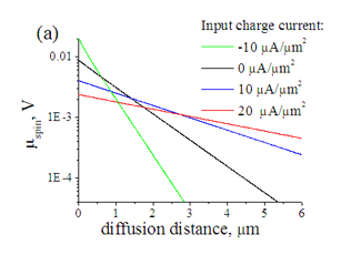
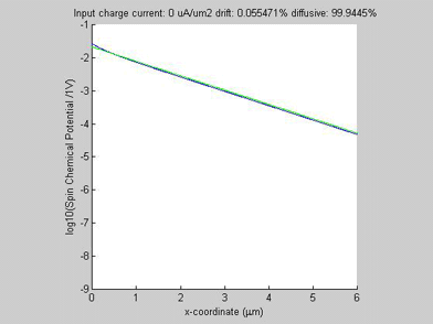
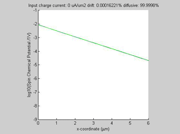
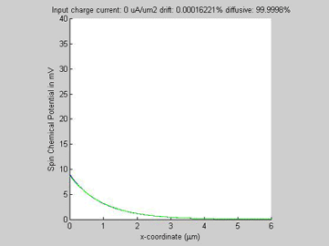
Fig. 1 The gain/damping of diffusive spin current by drift charge current. Input spin current is 2 mA/mm2. (a) Spin chemical potential |
||
|
||
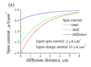
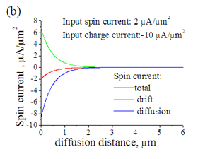
| Fig. 2. The total, drift and diffusion spin currents in case when the drift current flows (a) along diffusion current (b) opposite to diffusion current |
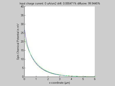
Figure 1(a) shows the calculated spin chemical potential ![]() for different values of the input charge current. For any input charge current, log(
for different values of the input charge current. For any input charge current, log(![]() ) is a straight line. This means that despite the fact that the spin transport in semiconductors is described by a set of non-linear equations and there is a significant interaction between the charge and spin currents, still the decay of the spin chemical potential
) is a straight line. This means that despite the fact that the spin transport in semiconductors is described by a set of non-linear equations and there is a significant interaction between the charge and spin currents, still the decay of the spin chemical potential ![]() is practically exponential, meaning that the spin transport can be described by an effective spin diffusion length. As can be seen from Fig. 1 (a), the effective spin diffusion length increases when the charge and spin currents flow in the same direction, and the effective spin diffusion length decreases, when the charge and spin currents flow in the opposite directions. When the charge current flows along the spin current, the spin current gains from the charge current so that the spin relaxation becomes slower and the spin length becomes longer. For the opposite direction of the charge current, the spin current is damped by the charge current so that the spin relaxation becomes faster and the spin length becomes shorter. It was calculated that the effective spin length does not depend on the magnitude of the input spin current.
is practically exponential, meaning that the spin transport can be described by an effective spin diffusion length. As can be seen from Fig. 1 (a), the effective spin diffusion length increases when the charge and spin currents flow in the same direction, and the effective spin diffusion length decreases, when the charge and spin currents flow in the opposite directions. When the charge current flows along the spin current, the spin current gains from the charge current so that the spin relaxation becomes slower and the spin length becomes longer. For the opposite direction of the charge current, the spin current is damped by the charge current so that the spin relaxation becomes faster and the spin length becomes shorter. It was calculated that the effective spin length does not depend on the magnitude of the input spin current.
Figure 2(a) shows the diffusion spin current, the drift spin current and their sum for the case when the drift current flows along the direction of the diffusion current. The polarity of the drift and diffusion spin currents are the same and the magnitude of each current is smaller than the magnitude of total spin current. Figure 2(b) shows the diffusion spin current, the spin-current component of the drift current and their sum for the case when the drift and diffusion currents flow in opposite directions. The polarities of the drift and diffusion spin currents are opposite and the magnitudes of both diffusion and spin currents are substantially larger than the magnitude of the total spin current.
The physical mechanism for the gain/damping of the spin current by the charge current is described as follows. The spin selectivity beta in semiconductors is a function the spin accumulation![]() as
as
As was explained here, in materials with non-zero spin selectivity beta the drift current is spin-polarized and the magnitude of the spin-current component of the drift current is linearly proportional to beta
![]()
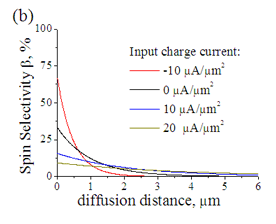
This means that in the semiconductor the drift current is spin-polarized, only when it flows together with the diffusion spin current. Only when there is a diffusion spin current,![]() . Along the diffusion direction of spin current the spin accumulation exponentially decays and consequently the spin selectivity beta decays as well. Figure 1 (b) shows the spin selectivity beta for different values of the input charge current. Since beta decreases, the spin component of the drift current decreases as well. Because of the spin conservation law, the spins are converted from a drift current to a diffusion current. When the polarity of the converted spins is the same as the spin polarity of diffusion current, the diffusion current gains the spins and the decay of diffusion current becomes slower. When the polarity of the conversion is different, the diffusion current is damped and the decay of diffusion current becomes faster.
. Along the diffusion direction of spin current the spin accumulation exponentially decays and consequently the spin selectivity beta decays as well. Figure 1 (b) shows the spin selectivity beta for different values of the input charge current. Since beta decreases, the spin component of the drift current decreases as well. Because of the spin conservation law, the spins are converted from a drift current to a diffusion current. When the polarity of the converted spins is the same as the spin polarity of diffusion current, the diffusion current gains the spins and the decay of diffusion current becomes slower. When the polarity of the conversion is different, the diffusion current is damped and the decay of diffusion current becomes faster.
A feature of the spin –current component of the drift currents is that it does not decay with propagation distance. For example, in the case of ferromagnetic metals the spin-current component of the drift current is the same over all flow path. Therefore, the spin relaxation has no influence on the spin drift current. Only the spin diffusion current decays with propagation distance (decay rate is described by the spin diffusion length). A spin information is transfered by a drift current without any loss. It starts to say only when the spin information is coverted into diffusion current. Therefore, the smaller magnitude of spin diffusion current is, the slower the spin relaxation becomes and longer the distance the spin information can be transfered (See Fig. 2).
The conversion of spin drift current into the spin diffusive current is called a spin injection. The spin injection is known to occur at a boundary between a ferromagnetic metal and a non-magnetic metal. In the case of semiconductors it can be considered that the spin injection may occur over all volume of the semiconductor.
In the case when drift and charge currents flow in the same direction, the sign of the spin converted from drift current into diffusive current is the same as that of diffusive current. Therefore, the drift current assists the spin diffusion and the effective spin diffusion length becomes longer. In the case when the drift current flows in opposite direction to the diffusive spin current, the converted spin is of opposite sign, the drift current hinders the spin diffusion and the effective spin diffusion length becomes shorter.
In all examples, the animated parameter is the input charge current (shown on the top of the figures). Also, on the top of each figure a ratio of the drift and diffussion spin currents is shown. The x-coordinate is the diffusion distance. For comparison the green plot shows a spin transport in the case if the conductivity of the semiconductor would be not spin-dependent (beta=0).
The spin and charge currents flow in the same direction.
 |
 |
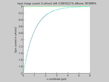 |
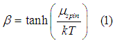
Fig.3a log10( |
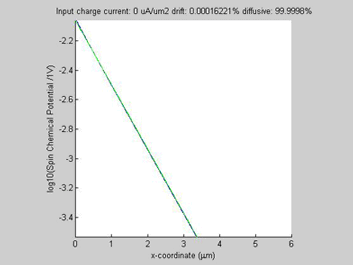
Fig.3b. Spin chemical potential |
Fig.3c Diffusion spin current (red line), drift spin current (green line), total spin current (blue line) the spin carent in the imaginary case of beta=0 (light-blue line). |
Figure 3c shows the diffusion, drift and total spin current. When the input charge current increases, ![]() increases, beta increases (See Eqn.1) and as a consequence the ratio of drift spin current to diffusion spin current increases( See Eqn.2). Since the total input spin current is fixed, the amount of the diffusion spin current decreases. Since the spin relaxation affect only the diffusion spin current and it does not affect the drift spin current, the spin relaxation becomes weaker when the magnitude of charge current increases. That is the reason for the elongation the spin diffusion length.
increases, beta increases (See Eqn.1) and as a consequence the ratio of drift spin current to diffusion spin current increases( See Eqn.2). Since the total input spin current is fixed, the amount of the diffusion spin current decreases. Since the spin relaxation affect only the diffusion spin current and it does not affect the drift spin current, the spin relaxation becomes weaker when the magnitude of charge current increases. That is the reason for the elongation the spin diffusion length.
The spin and charge currents flow in the oposite directions.
 |
 |
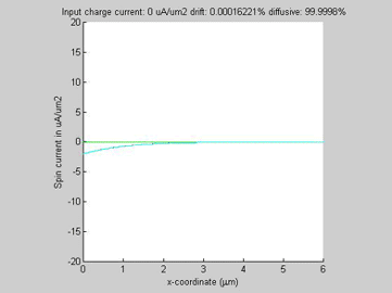 |
Fig.4a log10( |
Fig.4b. Spin chemical potential |
Fig.4c Diffusion spin current (red line), drift spin current (green line), total spin current (blue line) the spin carent in the imaginary case of beta=0 (light-blue line). |
In the case of opposite directions of the spin and charge currents, the drift and diffusion spin currents have opposite polarities and magnitudes larger than magnitude of the total spin current. When the input charge current increases, the diffusion spin relaxation becomes faster and as a consequence the effective spin diffusion length becomes shorter.
 |
|
Fig.5a log10( |
Fig.5b. Spin chemical potential |
As was explained here, in semiconductors there is a threshold spin current, above which the spin diffusion stops. The threshold spin current increases when the spin diffusion length in the semiconductor decreases. Since the effective diffusion length can be modulated by a charge current, the charge current may turn the diffusion spin current to or out of the threshold conditions, when the spin diffusion is stopped and a region of high spin and charge accumulation is formed. As result, the charge current may switch the spin diffusion on and off.
In case when the flow directions of the spin and charge currents are opposite, the diffusive spin current increases when the input charge current increases (See Fig.5). Therefore, the threshold spin current becomes smaller. For a fixed spin current by increasing a charge current the threshold condition may be reached. This configuration should be used when it is necessary to control spin diffusion by charge current.
In the case when the flow directions of the spin and charge currents are the same, the threshold input spin current becomes larger with increasing charge current. This configuration should be used when it is necessary to transfer a larger amount of spin current through the semiconductor.
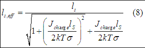
Even though spin/charge transport in semiconductors is described by a set of non-linear equations, it is possible to find the analytical expression for the effective spin diffusion length. It is necessary to use several approximations. However, in many cases the analytical expression for the effective diffusion length is a good approximation, which describes well the spin transport in semiconductors.
We use Eqn (7b) from here and Eqn. (7) from here
Substituting Eqn. (7(b)) into Eqn. (7) gives
![]()
or
![]()
In order to solve Eqn. (3) the following approximations are used. The conductivity and charge current are assumed to be a constant throughout the material. The spin current is assumed to be sufficiently below the threshold current ![]() . Therefore, the Eqn. (3) is simplified to
. Therefore, the Eqn. (3) is simplified to
Next, we differentiate the Eqn. (7e) obtained here
In the case of a small spin accumulation when  , Eqn.(5) is simplified to
Substituting (6) into (4) gives
Searching for solution of (7) in form

the effective spin diffusion length is found as
From (8) the charge current required to increase the spin diffusion length 2 times will be
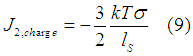
The current to decrease the spin diffusion length 2 times will be
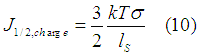
In the case of n-Si, at T=300 K mobility=1450 cm2/V/s and spin diffusion length of 1 um
![]()
where N is the doping concentration. For example, for doping concentration N=1E17 1/cm3, charge current to increase spin diffusion length in 2 times is 0.009 mA/um2. It is a relatively small current. For example, in the case of the Spin-Transfer-Torque Magnetic Random Access Memory STT-MRAM the threshold current for the magnetization reversal is about 10 mA/um2.
It should be noticed that the smaller the conductivity or the longer the spin diffusion length or the lower the temperature, the smaller the charge current required to change the spin diffusion length.
 |
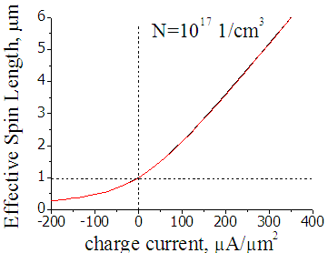 |
Fig.7 Effective spin length in n-Si (doping 1E16 1/cm3). Black line is calculated by Eqn.(8), red and blue lines are calculated by FDM. Input spin current 2 uA |
Fig.8. Effective spin length in n-Si (doping 1E17 1/cm3). Black line is calculated by Eqn.(8), red line is calculated by FDM. Input spin current 50 uA |
Figures 7 and 8 shows the effective spin diffusion length in n-Si with doping concentartion of 1E16 cm-3 and 1E17 cm-3, respectively. The black line is obtained by fitting the FDM solutions of Fig.1. The red line is calculated from Eqn. (8). The difference between the lines is less than 1 %. Therefore, despite the somewhat rough approximations used, Eqn. (8) well describes the interaction between the spin and charge currents in semiconductors in the majority of cases.
I will try to answer your questions as soon as possible

 It is important!!!! All data on this page are calculated based on the model of the spin-up/spin-down bands. The model of the spin-up/spin-down bands ignores
  For the modified model, which includes all above-mentioned facts,