Dr. Vadym Zayets
v.zayets(at)gmail.com
My Research and Inventions
click here to see all content |

Dr. Vadym Zayetsv.zayets(at)gmail.com |
|
 |
more Chapters on this topic:IntroductionTransport Eqs.Spin Proximity/ Spin InjectionSpin DetectionBoltzmann Eqs.Band currentScattering currentMean-free pathCurrent near InterfaceOrdinary Hall effectAnomalous Hall effect, AMR effectSpin-Orbit interactionSpin Hall effectNon-local Spin DetectionLandau -Lifshitz equationExchange interactionsp-d exchange interactionCoercive fieldPerpendicular magnetic anisotropy (PMA)Voltage- controlled magnetism (VCMA effect)All-metal transistorSpin-orbit torque (SO torque)What is a hole?spin polarizationCharge accumulationMgO-based MTJMagneto-opticsSpin vs Orbital momentWhat is the Spin?model comparisonQuestions & AnswersEB nanotechnologyReticle 11
more Chapters on this topic:IntroductionTransport Eqs.Spin Proximity/ Spin InjectionSpin DetectionBoltzmann Eqs.Band currentScattering currentMean-free pathCurrent near InterfaceOrdinary Hall effectAnomalous Hall effect, AMR effectSpin-Orbit interactionSpin Hall effectNon-local Spin DetectionLandau -Lifshitz equationExchange interactionsp-d exchange interactionCoercive fieldPerpendicular magnetic anisotropy (PMA)Voltage- controlled magnetism (VCMA effect)All-metal transistorSpin-orbit torque (SO torque)What is a hole?spin polarizationCharge accumulationMgO-based MTJMagneto-opticsSpin vs Orbital momentWhat is the Spin?model comparisonQuestions & AnswersEB nanotechnologyReticle 11
more Chapters on this topic:IntroductionTransport Eqs.Spin Proximity/ Spin InjectionSpin DetectionBoltzmann Eqs.Band currentScattering currentMean-free pathCurrent near InterfaceOrdinary Hall effectAnomalous Hall effect, AMR effectSpin-Orbit interactionSpin Hall effectNon-local Spin DetectionLandau -Lifshitz equationExchange interactionsp-d exchange interactionCoercive fieldPerpendicular magnetic anisotropy (PMA)Voltage- controlled magnetism (VCMA effect)All-metal transistorSpin-orbit torque (SO torque)What is a hole?spin polarizationCharge accumulationMgO-based MTJMagneto-opticsSpin vs Orbital momentWhat is the Spin?model comparisonQuestions & AnswersEB nanotechnologyReticle 11
more Chapters on this topic:IntroductionTransport Eqs.Spin Proximity/ Spin InjectionSpin DetectionBoltzmann Eqs.Band currentScattering currentMean-free pathCurrent near InterfaceOrdinary Hall effectAnomalous Hall effect, AMR effectSpin-Orbit interactionSpin Hall effectNon-local Spin DetectionLandau -Lifshitz equationExchange interactionsp-d exchange interactionCoercive fieldPerpendicular magnetic anisotropy (PMA)Voltage- controlled magnetism (VCMA effect)All-metal transistorSpin-orbit torque (SO torque)What is a hole?spin polarizationCharge accumulationMgO-based MTJMagneto-opticsSpin vs Orbital momentWhat is the Spin?model comparisonQuestions & AnswersEB nanotechnologyReticle 11
more Chapters on this topic:IntroductionTransport Eqs.Spin Proximity/ Spin InjectionSpin DetectionBoltzmann Eqs.Band currentScattering currentMean-free pathCurrent near InterfaceOrdinary Hall effectAnomalous Hall effect, AMR effectSpin-Orbit interactionSpin Hall effectNon-local Spin DetectionLandau -Lifshitz equationExchange interactionsp-d exchange interactionCoercive fieldPerpendicular magnetic anisotropy (PMA)Voltage- controlled magnetism (VCMA effect)All-metal transistorSpin-orbit torque (SO torque)What is a hole?spin polarizationCharge accumulationMgO-based MTJMagneto-opticsSpin vs Orbital momentWhat is the Spin?model comparisonQuestions & AnswersEB nanotechnologyReticle 11
more Chapters on this topic:IntroductionTransport Eqs.Spin Proximity/ Spin InjectionSpin DetectionBoltzmann Eqs.Band currentScattering currentMean-free pathCurrent near InterfaceOrdinary Hall effectAnomalous Hall effect, AMR effectSpin-Orbit interactionSpin Hall effectNon-local Spin DetectionLandau -Lifshitz equationExchange interactionsp-d exchange interactionCoercive fieldPerpendicular magnetic anisotropy (PMA)Voltage- controlled magnetism (VCMA effect)All-metal transistorSpin-orbit torque (SO torque)What is a hole?spin polarizationCharge accumulationMgO-based MTJMagneto-opticsSpin vs Orbital momentWhat is the Spin?model comparisonQuestions & AnswersEB nanotechnologyReticle 11
more Chapters on this topic:IntroductionTransport Eqs.Spin Proximity/ Spin InjectionSpin DetectionBoltzmann Eqs.Band currentScattering currentMean-free pathCurrent near InterfaceOrdinary Hall effectAnomalous Hall effect, AMR effectSpin-Orbit interactionSpin Hall effectNon-local Spin DetectionLandau -Lifshitz equationExchange interactionsp-d exchange interactionCoercive fieldPerpendicular magnetic anisotropy (PMA)Voltage- controlled magnetism (VCMA effect)All-metal transistorSpin-orbit torque (SO torque)What is a hole?spin polarizationCharge accumulationMgO-based MTJMagneto-opticsSpin vs Orbital momentWhat is the Spin?model comparisonQuestions & AnswersEB nanotechnologyReticle 11
more Chapters on this topic:IntroductionTransport Eqs.Spin Proximity/ Spin InjectionSpin DetectionBoltzmann Eqs.Band currentScattering currentMean-free pathCurrent near InterfaceOrdinary Hall effectAnomalous Hall effect, AMR effectSpin-Orbit interactionSpin Hall effectNon-local Spin DetectionLandau -Lifshitz equationExchange interactionsp-d exchange interactionCoercive fieldPerpendicular magnetic anisotropy (PMA)Voltage- controlled magnetism (VCMA effect)All-metal transistorSpin-orbit torque (SO torque)What is a hole?spin polarizationCharge accumulationMgO-based MTJMagneto-opticsSpin vs Orbital momentWhat is the Spin?model comparisonQuestions & AnswersEB nanotechnologyReticle 11
more Chapters on this topic:IntroductionTransport Eqs.Spin Proximity/ Spin InjectionSpin DetectionBoltzmann Eqs.Band currentScattering currentMean-free pathCurrent near InterfaceOrdinary Hall effectAnomalous Hall effect, AMR effectSpin-Orbit interactionSpin Hall effectNon-local Spin DetectionLandau -Lifshitz equationExchange interactionsp-d exchange interactionCoercive fieldPerpendicular magnetic anisotropy (PMA)Voltage- controlled magnetism (VCMA effect)All-metal transistorSpin-orbit torque (SO torque)What is a hole?spin polarizationCharge accumulationMgO-based MTJMagneto-opticsSpin vs Orbital momentWhat is the Spin?model comparisonQuestions & AnswersEB nanotechnologyReticle 11
more Chapters on this topic:IntroductionTransport Eqs.Spin Proximity/ Spin InjectionSpin DetectionBoltzmann Eqs.Band currentScattering currentMean-free pathCurrent near InterfaceOrdinary Hall effectAnomalous Hall effect, AMR effectSpin-Orbit interactionSpin Hall effectNon-local Spin DetectionLandau -Lifshitz equationExchange interactionsp-d exchange interactionCoercive fieldPerpendicular magnetic anisotropy (PMA)Voltage- controlled magnetism (VCMA effect)All-metal transistorSpin-orbit torque (SO torque)What is a hole?spin polarizationCharge accumulationMgO-based MTJMagneto-opticsSpin vs Orbital momentWhat is the Spin?model comparisonQuestions & AnswersEB nanotechnologyReticle 11
|
Band Current. Magnetic Material. Spin and Charge TransportThe band current is the major electron transport mechanism in the bulk metal. It occurs because of movent of electrons between scatterings. It is very efficient transport mechanism. A small injection conductivity σinjection, zero detection conductivity σdetection=0 and independence of the ordinary conductivity σcharge on spin polarization of the electron gas are distinguished features of the band current.
|
Two mechanisms of the Spin&Charge transport by Conduction Electrons.(Mechanism 1) Band Current. Origin: Movement of electrons between scatterings. Efficiency: high(Mechanism 2) Scattering current. Origin: electron scatterings from one state to another. Efficiency: lowclick here or on animated picture to enlarge it |
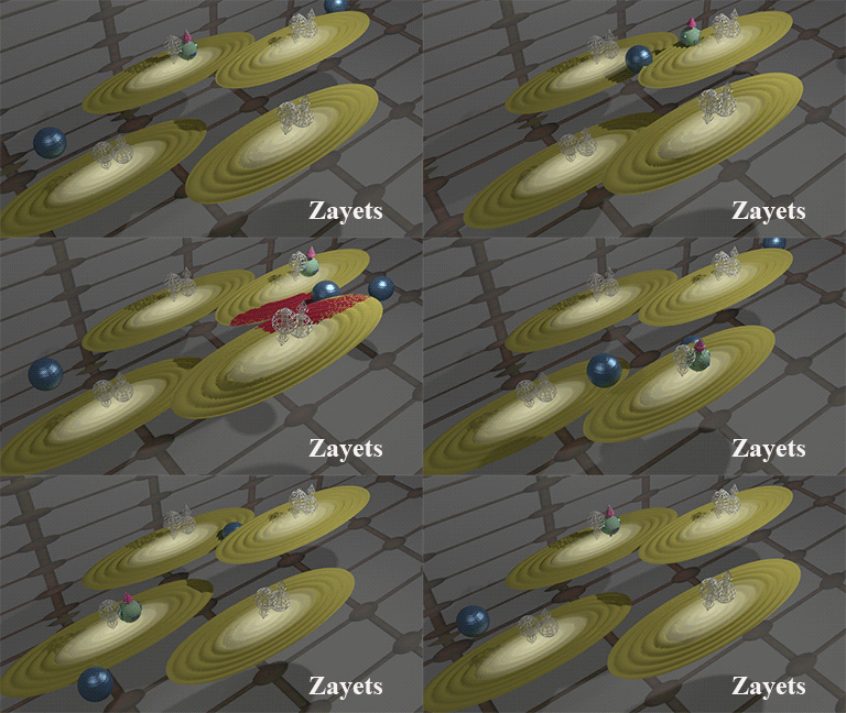 |
Blue balls represent defects. Brown ellipse shows distribution of wave function of the conduction electrons. A scattering occurs when wave functions of two states are overlapped (shown in red color) Note: An "electron" current is shown. It is the transport of electrons with an energy higher than the Fermi energy. The "hole" current is the current of electrons with an energy lower than the Fermi energy. The" hole" current of the conduction electrons is shown here. |
Results in short
1 transport mechanism:
The band current is the major transport mechanism in the bulk of a conductor.
2 Ordinary charge conductivity σcharge: (The Ohm law).
The electrons at the Fermi energy are most effective for the transferring of the charge. Above and below the Fermi energy the ordinary conductivity sharply decreases.
3. Spin-diffusion conductivity σspin: (Spin diffusion).
The σspin is always larger than the σcharge.
4. Detection conductivity σdetection: (Spin detection) (Charge accumulation along spin diffusion)
In a semiconductor and a metal the detection conductivity is zero![]() ;
;
5 Injection conductivity σinjection: (Spin polarization of an electrical current) (Spin transfer by an electrical current)
It is large in a semiconductor and it is small in a metal.

Origin of Band Current |
||||
| The band current occurs when the number of the electrons moving in one direction is not equal to the number of the running-wave electrons moving in opposite directions. | ||||
|
The band current occurs when the number of the electrons moving in one direction is not equal to the number of the electrons moving in opposite direction.
This current occurs because of movent of electrons between scatterings.
No. The localized d-electrons do not participate. Also, the standing-wave conduction electrons do not participate in the band current (See here).
All conduction (delocalized) electrons in a solid can be either standing-wave electrons or running-wave electrons. Only the running-wave electrons contributes to this current, the standing-wave electrons does not contribute. (See details here)
A. It is the major spin/charge transport mechanism in a bulk of a metal a a semiconductor. Additionally, it is the major transport mechanism of a low-resistivity contact.
![]() 1. Band current is the major transport mechanism in a bulk of a metal and a semiconductor.
1. Band current is the major transport mechanism in a bulk of a metal and a semiconductor.
Only another possible current is the scattering current. It is about 2-4 orders in magnitude less effective than the band current.
![]() 2. Band current is the major transport mechanism through a low-resistivity contact between two metals.
2. Band current is the major transport mechanism through a low-resistivity contact between two metals.
Even though at a contact between two metals, the conductivity of the band current always become smaller, for a low-resistivity contact it is still larger than the conductivity of the scattering current.
The drift current flows along gradient of the chemical potential ∇μ .
The diffusion current current flows along gradient of the spin polarization∇sp .
This page describes only the when there are no standing-wave electrons and the band electrons are running-wave electrons (Ideal case)
The standing-wave electrons have a substantial influence on spin properties of the band current. As example See the current in the vicinity of interface and current in a conductor with defects.
Drift band current |
|||||||||
|
|||||||||
| The data were calculated from Eqs.(1.5) and Eqs.(1.7) |
The drift current flows along an applied electrical field. The drift current flows from a drain ("+" electrical potential) towards a source ("-" electrical potential).
1. Charge drift current (ordinary current). The ordinary conductivity σcharge.
The ordinary conductivity significantly depends on electron energy (See Fig.20). The electrons at the Fermi energy are effective for the transfer of the charge. The state conductivity for them is highest. Above and below the Fermi energy the ordinary conductivity sharply decreases.
The ratio of state conductivity at given energy to the state conductivity at the Fermi energy:
1) ± kT → 78.6 %
2) ± 2kT → 41.9 %
3) ± 3kT → 18.0 %
4) ± 4kT → 7.0 %
5) ± 5kT → 2.6 %
![]() The contribution to the ordinary conductivity of electrons at energies 5kT above/below the Fermi energy is near 50 times smaller than the contribution of electrons at the Fermi energy. It is the primary reason why the conductivity of a metal is much higher than the conductivity of a semiconductor.
The contribution to the ordinary conductivity of electrons at energies 5kT above/below the Fermi energy is near 50 times smaller than the contribution of electrons at the Fermi energy. It is the primary reason why the conductivity of a metal is much higher than the conductivity of a semiconductor.
2. Spin drift current. The injection conductivity σinjection. Spin polarization of current.
The injection conductivity σinjection (See Fig.21) describes the drift of the spins along an electrical current and the spin polarization of an electrical current. When an electrical current flows from one region to another region, the spin accumulation in one region may increase and in another region it may decrease. When two regions belong to different metals, such effect is called the spin injection. The polarity of the spin injection is different for electrons, which energy is lower and higher than the Fermi energy. This means that electrons of different energies transform spins in opposite directions. In a metal the electron density is nearly constant at the Fermi energy and there is an almost-equal amount of electrons, which transform the spins in the opposite directions. As result, the spin polarization of electrical current in a metal is near zero and an electrical current nearly does not transform the spin at all. Only in the case when in a metal there is a non-zero gradient of the density of state at the Fermi energy and there is a small difference of amounts of electrons bellow and above the Fermi energy, the value of spin injection becomes non-zero and an electrical current may transform the spins. However, in a metal it is still very inefficient. It means that in a metal the spin polarization of electrical current is always substantially smaller than the spin polarization of the electron gas (See Fig.22). In contrast, in a semiconductor the σinjection is large and it is near equal to the ordinary charge conductivity σcharge. It also means that in a semiconductor the spin polarization of an electrical current is near equal to the spin polarization of the electron gas. In a non-degenerate n-type semiconductor, the Fermi energy is below the conduction band and all conduction electrons are at energies above the Fermi energy. In this case the spins is transferred from a "-" to a "+" electrode. It is similar to transfer of the spin by negatively-charged particles in vacuum, when the spin and the negative charge are carried in the same direction. In a non-degenerate p-type semiconductor, the Fermi energy is above the conduction band and all conduction electrons are at energies below the Fermi energy. In this case the spins are transferred from a "+" to a "-" electrode. It is similar to transfer of the spin by positively-charged particles in vacuum, when the spin and the positive charge are carried in the same direction.
Diffusion band current |
| The data were calculated from Eqs.(1.5) and Eqs.(1.7) |
Diffusion spin current is a current, which flows along a gradient of spin accumulation.
1. Spin diffusion current . The spin conductivity σspin.
It describes the flow of the spins from a region of a higher spin accumulation to a region of a smaller spin accumulation.
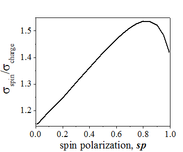
The spin conductivity σspin is larger than the ordinary conductivity charge conductivity( See Fig. 23). Figure 25 shows the the ratio of spin conductivity σspin to ordinary charge conductivity σcharge. Above and below the Fermi energy these conductivities are almost equal. The largest difference between them is at the Fermi energy and it is larger for a larger spin polarization sp of the electron gas. At spin polarization sp=75% , the σspin can be 2.5 times larger than σcharge. The reason of the difference between σspin and σcharge. is a higher density of spin-polarized electrons at the Fermi energy (See spin statistics).
2. The detection conductivity σdetection. The charge accumulation along spin diffusion.
The detection conductivity σdetection describes the diffusion of the charge along a gradient of the spin accumulation. When spin-polarized electrons diffuse from a region of a higher spin-accumulation to a region a lower spin accumulation, additionally there is a current of spin-unpolarized electrons, which flows exactly in the opposite direction. When the opposite currents of the spin-polarized and spin-unpolarized electrons are not equal, the charge is accumulated along the spin-diffusion (See here). This charge accumulation can be measured electrically. Since an amount of the charge accumulation is proportional to spin diffusion current, the value the spin diffusion current can be estimated from such electrical measurements. As can be seen from Fig.24, the σdetection equals to zero for all energies. This means that in the bulk of a defect-free conductor there is always an exact balance between opposite currents of spin-polarized and spin-unpolarized electrons.
The Fermi energy EFermi crosses one or several bands. As result, the density of state is nearly constant in region EFermi-10kT<E<EFermi+10kT.
(1) Only conduction electrons in energy range EFermi-3kT<E<EFermi+3kT.mainly contribute to ordinary σcharge and spin- diffusion σspin conductivities.
(2) Both the ordinary σcharge and spin- diffusion σspin conductivities are large. They do not dependent on charge accumulation. The σcharge does depend on spin-accumulation. The σspin conductivities slightly increases for larger spin accumulation (max 50 % increase).
(3) The spin polarization of an electrical current is significantly smaller than the spin polarization of the electron gas. The injection conductivity is much smaller than the ordinary conductivity σinjection<<σcharge
(4) No charge accumulation along spin diffusion. σdetection=0.
The Fermi energy EFermi in the band gap. All states of conduction electrons are either substantially above or below the Fermi energy EFermi.
(1) All conduction electrons contribute to ordinary σcharge and spin σspin conductivities in case of a n-type semiconductor and only electrons of half-filled states contribute in the case of a p-type semiconductor.
(2) Both the ordinary σcharge and spin- diffusion σspin conductivities are equal and relatively small. They both significantly depend on the charge accumulation and they do not depend on spin accumulation. σcharge = σspin
(3) The spin polarization of an electrical current is equal to the spin polarization of the electron gas. The injection conductivity is equal to the ordinary conductivity σinjection=σcharge.
(4) No charge accumulation along spin diffusion. σdetection=0.

Spin/Charge Transport Equations |
 |
From the Boltzmann Transport Equations, the ordinary charge conductivity σcharge, spin-diffusion conductivity σspin, detection conductivity σdetection and injection conductivity σinjection can be found
The Boltzmann transport equations are described here.
In order to describe the feature of the band current, only two terms of the general Boltzmann transport equations have to be used.
The simplified Boltzmann transport equations are :
where Fi are distribution functions and τk is the momentum relaxation time. The subscript "i" labels the distribution functions for the group of spin-polarized electrons as "TIA", group of spin-unpolarized electrons as "TIS" and electrons of full-filled states as "full".
The solution of Eqs. (1.1) (See Appendix 1) is:
where ![]() is the band current of spin -polarized electrons ,
is the band current of spin -polarized electrons , ![]() is the band current of spin-unpolarized electrons and
is the band current of spin-unpolarized electrons and ![]() is the band current of electrons occupying the full-filled states.
is the band current of electrons occupying the full-filled states.
![]() are are equilibrium distribution functions of groups of spin-polarized electrons, spin-unpolarized electrons and electrons occupying the full-filled states, correspondingly. They are calculated here.
are are equilibrium distribution functions of groups of spin-polarized electrons, spin-unpolarized electrons and electrons occupying the full-filled states, correspondingly. They are calculated here.
The band current occurs, because of the movement of band electrons (delocalized conduction electrons) in space. The movement of an electron literally means that if at time t the electron is at point x, at time t+dt the electron will be at point ![]() , where vx is the electron speed along the direction of the x-axis.
, where vx is the electron speed along the direction of the x-axis.
The change of electron distribution F(x) at point x can be described as
![]()
where ![]() describes the movement of electrons to point x from point
describes the movement of electrons to point x from point ![]() and
and ![]() describes movement of electrons from point x to point
describes movement of electrons from point x to point ![]()
In the case of a short time interval dt, Eq. (14.1) can be simplified as

or

Taking into the account that the electron can move not only in the x-direction, but in any direction gives

Using the he relaxation-time approximation and substituting of Eq. (14.4 ) into the Boltzmann transport equations Eqs. (1.1) gives

The solution of the Boltzmann transport equations for the band current is
![]()

The current due to movement of one electron in volume V is

where q is the charge of an electron.
Integrating Eq. (14.8a) over all quantum states and using Eq. (14.7), the band current can be calculated as

In equilibrium there should be no current:

The condition (A1.8) was used to simplify Eq. (A1.7).
Similarly the currents flowing along ji,|| and perpendicularly ji,⊥to ![]() are calculated as
are calculated as

Since ji,⊥=0, the current flows only along ![]() and first equation of Eqs. (A1.10), the band current can be calculated as
and first equation of Eqs. (A1.10), the band current can be calculated as

The explicit expressions for the band current of spin -polarized electrons![]() , the band current of spin-unpolarized electrons
, the band current of spin-unpolarized electrons![]() and the band current of electrons occupying the full-filled states
and the band current of electrons occupying the full-filled states![]() are
are

It is important! 
Integration in Eq (14.8) is only over states of running-wave electrons. The standing wave electrons should not be included into the integration.
How to include the standing-wave electrons in the integration of Eqs. (14.9) is shown here and here.
All three currents ![]() ,
, ![]() and
and ![]() transport the charge, but the spin is only transported by the current of the spin-polarized electrons
transport the charge, but the spin is only transported by the current of the spin-polarized electrons ![]() . Therefore, the charge current
. Therefore, the charge current ![]() and spin current
and spin current![]() can be calculated as
can be calculated as
Currents of electrons from groups of spin-polarized, spin-unpolarized electrons and electrons of full-filled states |
||||||||||
|
||||||||||
| Explanations of Figs. 41 and 42 are given under collapsed panel below (click on it to expand) |

There are only two independent variables: the chemical potential ![]() and the gradient the spin polarization sp, which describe special variation of the distribution function. Therefore, the gradients of the distribution functions can be calculated as:
and the gradient the spin polarization sp, which describe special variation of the distribution function. Therefore, the gradients of the distribution functions can be calculated as:

Using Eqs (1.4) and (1.2), the charge, injection, spin and detection conductivities are calculated from Eqs. (1.3) as
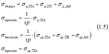
The conductivities at the right side of Eqs (1.5) are calculated as
where the script j denotes "μ,TIA", "μ,TIS", "μ,full", "sp,TIA", "sp,TIS", "sp,full". The σj(E) are defined as the state conductivities and are calculated as

In the following we calculate the charge , spin-diffusion , detection and injection conductivities from Eqs. (1.3) using Eqs. (1.4), and (1.2).
In order to simplify the solution and the analysis, two cases are calculated separately. At first, the drift current flowing along an electrical field is calculated. Next, the diffusion current flowing along a gradient of spin polarization is calculated.
case 1. The drift current.
In the case when there is a spatial gradient of the chemical potential μ, the gradient of the distribution function can be calculated as

Substituting Eqs. (4.1) into Eqs. (1.2) gives the drift current ![]() as
as

Similar as above, the subscript "i" labels the distribution functions for the group of spin-polarized electrons as "TIA", group of spin-unpolarized electrons as "TIS" and electrons of full-filled states as "full".
The definition of the drift current is

Comparison of Eq. (4.2) and Eq.(4.3) gives the conductivities of spin polarized electrons σµ,TIA, spin-unpolarized electrons σµ,TIS, and electrons of full-filled states σµ,full, for the drift current as
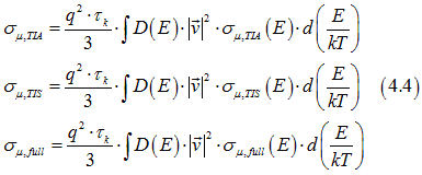
where the state conductivities σµ,TIA(E) , σµ,TIS(E) , σµ,full(E) are defined as
![]()
All conductivities of Eq.(4.5), which describe a drift current, are proportional to derivative of the energy distribution in respect to the electron energy.
Figures 41 shows the calculated state conductivities σµ,TIA(E) , σµ,TIS(E) , σµ,full(E). The state conductivity σµ,full(E) for a band current of electrons of full-filled states is positive for all energies. This means that the full-filled states are drifted from a “–“ source toward a “+” drain. It is similar to the movement of a negatively-charged particle in an electrical field in vacuum. The state conductivities σµ,TIA(E) , σµ,TIS(E) for a currents of electrons of half-filled states are positive for energies above the Fermi energy and they are negative for energies below the Fermi energy. This means that the drift direction of these states depends on their energy. The half-filled states of energies above the Fermi energy are drifted from a “–“ source toward a “+” drain. It is similar to the movement of a negatively-charged particle in an electrical field in vacuum. However, the half-filled states of energies below the Fermi energy are drifted in the opposite direction from a “+“ source toward a “-” drain. The drift becomes similar to the movement of a positively-charged particle in an electrical field in vacuum.
case 2. The diffusion current.
. In this case there is a spatial gradient of the spin polarization sp and the gradient of the distribution function can be calculated as

Substituting Eqs. (4.1) into Eqs. (1.2) gives the diffusion current ![]() as
as

The definition of the diffusion current is

Comparison of Eq. (4.7) and Eq.(4.8) gives the conductivities of spin polarized electrons σsp,TIA, spin-unpolarized electrons σsp,TIS, and electrons of full-filled states σsp,full, for the diffusion current as
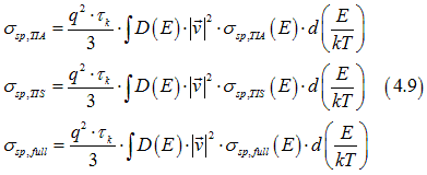
where the state conductivities σsp,TIA(E) , σsp,TIS(E) , σsp,full(E) are defined as

All conductivities of Eq.(4.10), which describe a drift current, are proportional to derivative of the energy distribution in respect to the electron energy.
Figures 42 show the calculated state conductivities σsp,TIA(E) , σsp,TIS(E) , σsp,full(E). The conductivity of the spin-polarized electrons σsp,TIA(E) is positive. It describes the simple fact that the spin-polarized electrons diffuse from a region of a higher spin accumulation into a region of a smaller spin accumulations. The conductivities of spin-unpolarized electrons σsp,TIS(E) and σsp,full(E) are negative. It means that the spin-unpolarized electrons diffuse in the opposite direction.
Notice the metal conductivity ![]() is defined as
is defined as  , where e is the charge of the electron.
How the calculations have been done?
In the bulk of a conductor, the equilibrium distribution functions are described by the spin statistics. It can be assumed that in a conductor with a low density of dislocations, there are no standing-wave electrons . All delocalized electrons are the running-wave electrons and all of them contribute to the running-wave electron currents. Therefore, the distribution functions of the spin statistics are used in Eqs. (14.16), (14.20) in order to calculate the state conductivities shown below.
In order to calculate the metal conductivities it is necessary to know the density of state D(E) of the metal (Eqs.(14.15) . The calculation of the unitless state conductivities does not require the density of state. Therefore, even without knowing the density of states of the metal, some conduction properties of the metal can be calculated and analyzed from the state conductivities. It is an advantage of using the state conductivities.
The normal conductivity σi can be calculated by integrating the state conductivity with the density of states D(E):

Conductivities, which describes spin and charge currents |
||||||||||||
|
||||||||||||
Charge or ordinary conductivity σcharge
The charge or ordinary conductivity σcharge significantly depends on electron energy. The electrons at the Fermi energy are most effective for the transport of the charge. The ordinary charge conductivity for them is largest. Above and below the Fermi energy the ordinary conductivity sharply decreases. For example, the contribution to the ordinary conductivity of electrons at energies 5kT above/below the Fermi energy is near 50 times smaller than the contribution of electrons at the Fermi energy. It is the primary reason why the conductivity of a metal is much higher than the conductivity of a semiconductor. The ordinary conductivity σcharge does not depend on the spin polarization sp of the electron gas.
Spin-diffusion conductivity σspin
The spin-diffusion conductivity σspin describes the diffusion of the spins along a gradient of spin accumulation. The spin conductivity σspin is larger than the ordinary charge conductivity σcharge. Above and below the Fermi energy, these conductivities become near equal. The largest difference between them is at the Fermi energy and it is larger for a larger spin polarization sp of the electron gas. At spin polarization sp=75% , the σspin can be 2.5 times larger than σcharge . The reason of the difference between σspin and σcharge is a higher density of spin-polarized electrons at the Fermi energy
injection conductivity σinjection
The injection conductivity σinjection describes the drift of the spins along an electrical current. It also defines the spin polarization of an electrical current. When an electrical current flows from one region to another region, the spin accumulation in one region may increase and in another region it may decrease. When two regions belong to different metals, such effect is called the spin injection. The polarity of the σinjection is different for electrons, energy of which is lower and higher than the Fermi energy. This means that electrons of different energies carry the spins in opposite directions. In a metal the electron density is nearly constant at the Fermi energy. Therefore, amounts of electrons, which carry the spin along an electrical current and in the opposite direction, are nearly equal. As result, the spin polarization of electrical current in a metal is near zero and an electrical current nearly does not transport the spin at all. Only in the case when in a metal there is a non-zero gradient of the density of state at the Fermi energy and there is a small difference of amounts of electrons bellow and above the Fermi energy, the value of σinjection becomes non-zero and an electrical current may transport the spins. However, in a metal it is still very inefficient. It means that in a metal the spin polarization of electrical current is always substantially smaller than the spin polarization of the electron gas. In contrast, in a semiconductor the σinjection is large and it is near equal to the ordinary charge conductivity σcharge . It also means that in a semiconductor the spin polarization of an electrical current is near equal to the spin polarization of the electron gas. In a non-degenerate n-type semiconductor, the Fermi energy is below the conduction band and all conduction electrons are at energies above the Fermi energy. In this case the spins is transported from a "-" to a "+" electrode. It is similar to the transport of the spin by negatively-charged particles in vacuum, when the spin and the negative charge are carried in the same direction. In a non-degenerate p-type semiconductor, the Fermi energy is above the conduction band and all conduction electrons are at energies below the Fermi energy. In this case the spins are transported from a "+" to a "-" electrode. It is similar to the transport of the spin by positively-charged particles in vacuum, when the spin and the positive charge are carried in the same direction.
detection conductivity σdetection
The detection conductivity σdetection describes the diffusion of the charge along a gradient of the spin accumulation. When spin-polarized electrons diffuse from a region with a higher spin-accumulation to a region with a lower spin accumulation, additionally there is a current of spin-unpolarized electrons, which flows exactly in the opposite direction. When the opposite currents of the spin-polarized and spin-unpolarized electrons are not equal, the charge is accumulated along the spin-diffusion. This charge accumulation can be measured electrically. Since an amount of the charge accumulation is proportional to spin diffusion current, the value the spin diffusion current can be estimated from such electrical measurements. The effect is called the spin detection. As can be seen from Fig.44, the σdetection equals to zero for all energies. This means that in the bulk of a defect-free conductor there is always an exact balance between opposite currents of spin-polarized and spin-unpolarized electrons
Spin-polarization of electrical current |
||
|
||
The relative spin polarization of an electrical current σinjection/ σcharge/sp. It describes the efficiency of the spin transfer by an electrical current. |
Semiconductors:
It equals to the spin-polarization of the electron gas
The reason:
There is only one type of carriers. It is either the electrons or the holes
Metals:
It is significantly smaller than the spin-polarization of the electron gas.
The reason:
There two types of carriers: the electrons and the holes. The electrons and the holes transport the spin in the opposite directions.
The spin-diffusion conductivity σspin describes transport of the spin in a diffusion spin current.
semiconductors:
It equals to the ordinary conductivity σcharge
Metals:
It is larger than the ordinary conductivity σcharge
The reason:
The larger amount of spin-polarized electrons at the Fermi energy (See here)
![]() What is difference between a drift current and a diffusion current?
What is difference between a drift current and a diffusion current?
Charge, spin-diffusion, injection and detection conductivities for electrons and holes |
||||
|
||||
Fig. 11. The charge, injection, detection and spin-diffusion conductivities for a running wave electron current in the bulk of a conductor with a low density of defects.(a) spin polarization sp=0.2 (b) spin polarization sp=0.85. The current of electrons of energy larger than the Fermi energy is defined as the electron current (blue area). The current of electrons of energy smaller than the Fermi energy is defined as the hole current (yellow area). The same data was used as in Fig.43 and Fig.44 |
||||
Currents of electrons from groups of spin-polarized, spin-unpolarized electrons and electrons of full-filled states |
||||
|
||||
| Fig.12. The conductivity of electrons of group of spin-polarized electrons (blue line), group of spin-unpolarized electrons and electrons of full-filled states for a a drift current. The same data was used as in Fig.41 and Fig.42 |
Both the “electrons” and the “holes” are absolutely identical particles. They both are half-filled states, in which one place is occupied by an electron and another place is empty. The only difference between “electrons” and the “holes” is their electron energy. The energy of an “electron” is above the Fermi energy EF and the energy of a “hole” is below EF. Depending on the electron energy, the properties of a half-filled state are substantially different. In an electrical current the "electrons", whose energy > EF , transport the charge and the spin from a "-" potential to a "+" potential similar to a current of negative-charged particles in vacuum. In contrast, the "holes", whose energy < EF, transfer the charge and the spin in the opposite direction from a "+" potential to a "-" potential similar to a current of positively-charged particles in vacuum. In a metal there are almost equal amounts of "holes" and the "electrons" and they transport spin in the opposite directions. As result, the transferring of the spin accumulation by an electric current is ineffective in the bulk of a metal.
In diffusion current the properties of the electrons and the holes are absolutely identical (See Fig.12 right).
Band Current of two types |
||||||
|
In drift current the properties of the electrons are very different. Below explanation is for the drift current (See Fig.12 left)
In a non-degenerate n-type semiconductor, the Fermi energy is below the conduction band and all states available for transport are at energies above the Fermi energy. In this case the conductivity σμ,full of the full-filled states is small and the major transport mechanisms is the transport of the half-filled states. A half-filled state is negatively charged and its spin is ½. Therefore, the half-filled states carry simultaneously the spin and the negative charge. It is similar to the movement an electron in vacuum, when the spin and the negative charge are carried in the same direction. For this reason, the conductivity in an n-type semiconductor is called the electron conductivity.
In a non-degenerate p-type semiconductor, the Fermi energy is above the valence band and all states available for transport are at energies below the Fermi energy. In this case both the full-filled and half-filled states substantially contribute to the transport. Since σμ,full is positive and σμ,TIE,σμ,TIS are negative, the full-filled and half-filled states transport a negative charge in opposite directions. The σμ,full is larger than σμ,TIE+σμ,TIS .Therefore, the charge conductivity σcharge is positive for all energies (Fig.11, blue curve) and in total the negative charge is transported from “-“ to “+”. The spin of a full-filled state is zero and only half-filled states carry the spin. The spin is drifted in the opposite direction to the drift direction of the negative charge. It is from “+” to”-“. It is similar to the movement a positive particle in vacuum, when the spin and the positive charge are carried in the same direction. The conductivity in a p-type semiconductor is called the hole conductivity.
In a metal the electron and hole conductivities are almost equal. The drift direction of the charge is the same for the electron and hole currents. It is a drift of a negative charge from “-“ to “+” or a drift of a positive charge from “+“ to “-”. In contrast, the drift of spin is in opposite directions for the hole and electron currents and the opposite spin currents nearly compensate each other. Therefore, in a metal the spin drift current is significantly smaller than the drift charge current and the spin polarization of the drift current is always significantly smaller than the spin polarization of the electron gas. It is different from the case of a semiconductor, where the spin polarization of the drift current is equal to the spin polarization of the electron gas.
 |
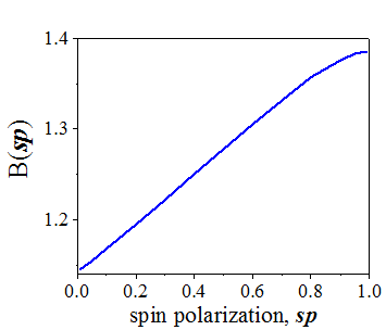 |
| The ratio of the spin-diffusion conductivity to the charge (ordinary) conductivity in a metal | Coefficient B(sp) as functions of the spin polarization of an electron gas (See 3d Eq. of (15.3)) |
In case when the Fermi energy is far from any band critical point, the density of states is nearly constant and the Fermi surface consists of only one band, the following approximation can be used

where ![]() and D_F are the electron speed and the density of states at the Fermi energy, respectively.
and D_F are the electron speed and the density of states at the Fermi energy, respectively.
Substituting Eq. (15.1) into Eqs. (1.6) and integrating gives the conductivities in the bulk of a metal with a low density of defects as
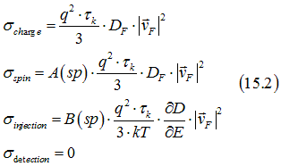
From Eqs. (15.2) the following ratios between the conductivities in the bulk of a metal are obtained
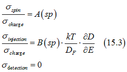
In comparison in the case of a non-degenerate semiconductor the conductivity ratios are

![]()
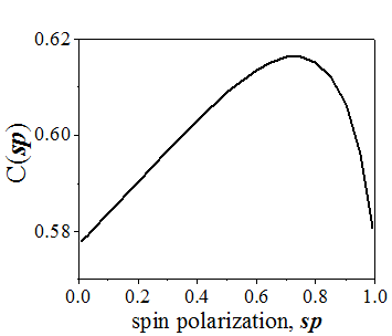 |
| The proportionality coefficient for calculation of the spin-diffusion length in a metal (See Eq. 15.5) |
Substituting Eq. (15.3) into Eq. (4.8) gives the spin-diffusion length in a non-magnetic metal as

Two mechanisms of the Spin/Charge transport: (1) Band current due to electron movement between scatterings (2) Scattering current due to electron movement after scatterings |
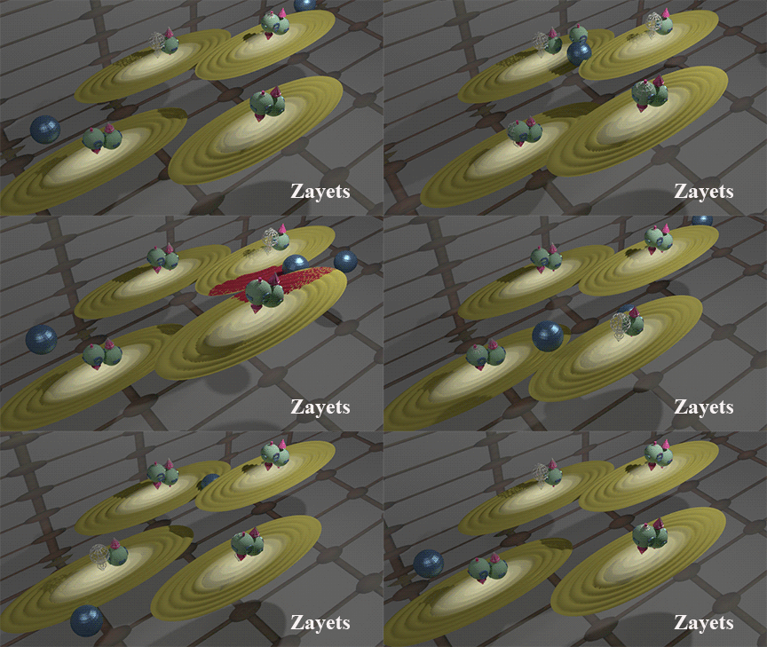 |
Blue balls represent defects. Brown ellipse shows distribution of wave function of the running-wave electrons. The case of the hole transport is shown. click here or on animated picture to enlarge it. |
Comparison of spin/charge transport mechanisms |
||||||||||||||||||||||||||||||||||||
|
||||||||||||||||||||||||||||||||||||
All above description in this page is for band current 1, when all conduction electrons are standing-wave electrons. |
The transport properties, which are described above on this page, are only valid for the case of transport in the bulk of a high-conductivity conductor without defects and multi-layers. This is the case when the periodicity of the crystal is not broken and all conduction electrons are running-wave electrons. When the number of defects decreases, the number of the standing-wave electrons increases as well. It significantly changes the properties of the spin transport. When the number of defects increases further, the scattering current become dominated. The spin transport properties of the scattering current are substantially different from that of the band current. In the following we discuss how the existence of the standing-wave electrons influences all conductivities .
A standing-wave electron. An example, an electron bouncing between two defects. |
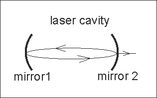
Standing-wave photon in laser cavity |
 |
|
The standing -wave electrons do not contribute to the band current!!When bouncing between defects, one electron, which moves forward, is firmly fixed to the electron, which moves backward. These coupled electrons do not move along crystal. Click on image to enlarge it |
Photon is reflecting back and forward between two mirrors forming a standing wave. When the photon passes through the semitransparent mirror, it becomes the running-wave photon. Similarly, a standing-wave electron is reflected between two defects (note, only one defect is sufficient to make a standing wave electron) |
It is important to emphasize that not all conduction electrons contribute to the band current. All conduction electrons can be divided into two different types: running-wave and standing-wave electrons. The effective length of the conduction electrons is rather long (See here). In a semiconductor it can be as long as a hundred of nanometers. In the case when an average distance between defects in a conductor is comparable with the effective length of a conduction electron, the electron may bounce back and forwards between defects. It is similar to the case of a photon, which are bouncing between walls of a resonator. When bouncing between defects, one electron, which moves forward, is firmly fixed to the electron, which moves backward. These coupled electrons do not move along crystal. They are fixed at position of defects. Importunately, when an electrical field is applied, still there is one electron moving forward and one electron moving backward. The electrical field does not change the ratio of electrons moving in opposite directions for this type of electrons. Therefore, these electrons do not contribute to the band current. These coupled electrons are defined as the standing-wave electrons. The electrons, which can move freely along crystal and which are not fixed to one position, are defined as the running-wave electrons. Only they contribute to the band current.
Running waves |
Standing waves |
|
 |
The running waves are moving in the space. A running-wave electron moves in the space. Since it moves, it transfers the spin and the charge.
|
The quantum mechanics does not require that an object with non-zero speed necessary moves in the space. One example is a standing wave, which has non-zero speed, does not move in the space. A standing wave can be decomposed as a sum of two waves running in opposite directions. The standing-wave electrons contribute only to the scattering conductivity. |
Yes. Both the standing-wave electron and the running-wave electrons are described by the spin-statistics,
It is because of a very large difference between scattering probabilities between a running-wave electron to a standing-wave electron and a running-wave electron to a localized electron. The sizes of a running-wave electron are a standing-wave electron are nearly the same. In contrast, the size of a localized electron is much smaller. The scattering probability between a running-wave electron to a standing-wave electron is nearly the same as scattering probability between two running-wave electrons. The scattering probability between a running-wave electron to a localized electron is very small.
![]() It is important that the scattering probability between a standing-wave electron to a localized electron is higher than between a running-wave electron to a localized electron. This is the reason why existence of the standing-wave electron enhances the sp-d exchange interactions
It is important that the scattering probability between a standing-wave electron to a localized electron is higher than between a running-wave electron to a localized electron. This is the reason why existence of the standing-wave electron enhances the sp-d exchange interactions
Mean-free path λmean or effective length of electron,
|
||
|
||
Fig. 3 .Mean-free path of spin-polarized (red line), spin-unpolarized electrons (black line), electrons of full-filled states (blue line)and states, which are not filled by any electrons (green line) in the bulk of a conductor with defects. The average distance between defects is 1 mm. (a) spin polarization sp=0.2; (b) spin polarization sp=0.85. There are more standing-wave electrons when the mean-free path λmean is longer. Click on image to enlarge it |
 How do we know how many standing-wave electrons and how many running-wave electrons??
The mean-free path is an important parameter, which determines the number of the standing-wave electrons in a conductor. The longer the effective length of electron is, the higher the probability is for the electron to bounce between defects or interfaces to form a standing-wave electron. Figure 3 shows the mean -free path of the conduction electrons in the bulk of a conductor with defects, which is calculated here. The λmean significantly increases for a full-filled states at energies EF-2kT and lower. Near the Fermi energy, all states have the same and rather short λmean The case of a large spin-polarization sp, when the λmean of spin-polarized electrons is longer, is an exception. Intuitively, the data of Fig. 3 can be understood as follows. Below the Fermi energy almost all states are full-filled states, which have no unoccupied places where an electron can be scattered into. There are only a few of half-filled states, which have one unoccupied place. The probability of an electron to be scattered from a full-filled states is very low, because most of time a full-filled state is surrounded by other full-filled states, into which an electron can not be scattered. Rarely a half-filled state is nearby and a scattering event may happen. Therefore, the life time of full-filled state is long and the λmean is long as well. In contrast, a half-state is always surrounded by full-filled states, from which an electron can be scattered into the half-filled state with a high probability. Therefore, both the life time and λmean are short for a half-filled state. Near the Fermi energy, all states have enough possibilities for scatterings and λmean is short for all states, except the case of a high spin polarization sp of electron gas. In this case almost all states near the Fermi energy are occupied by spin-polarized electrons. As was mentioned above, electrons can not be scattered between states occupied by spin-polarized electrons. It makes the life time and λmean of the spin-polarized electrons longer.
Influence of the standing-wave electrons on conductivities:
The existence of the standing-wave electrons affects all four conductivities σcharge, σspin, σinjection and σdetection. Since the standing-wave electrons do not participate in the band current, both the ordinary charge conductivity σcharge and the spin-diffusion conductivity σspin decrease. For example, the ordinary conductivity σcharge decreases in a conductor with defects and in the vicinity of an interface. Due to the existence of the standing-wave electrons at an interface between two metals, there is always a contact resistance between the metals even in the case when there is no energy barrier between them. When a thickness of a metal decreases, its conductivity σcharge becomes smaller because of an increase of the number of the standing-wave electrons. However, when the thickness becomes thinner than the mean-free path, the conductivity may become larger again because the transport changes to the 2D type. Because of the electron confinement, the electrons can not be scattered across the interface and they move only in one direction. As result, the number of standing-wave electrons decreases and the conductivities σcharge and σspin increase. For more details, see here and here
detection conductivity σdetection
Defect and interfaces are good for spin transport |
 |
Click on image to enlarge it.
|
As can be seen from Fig.3, the number of the standing-wave electrons significantly dependents on the electron energy. As consequence, the spin properties of the conductivity may change substantially. For example, the detection conductivity σdetection may become non-zero. As can be seen from Fig. 3, the mean-free path λmean of full-filled states is rather long for energies below EF-2kT. Therefore, many of electrons of these states are standing-wave electrons and they do not participate in the band current. The reason, why the detection conductivity σdetection is zero in Fig.44, is the exact balance of the opposite flows of spin-polarized and spin-polarized electrons along a gradient of spin accumulation. In a conductor with defects or in the vicinity of an interface, more spin-unpolarized electrons and less spin-polarized electrons become the standing-wave electrons. It breaks the balance and the σdetection becomes non-zero. This is the reason why the spin detection effect is only observed at a contact between metals, but not in the bulk of a metal.
injection conductivity, σinjection
The injection conductivity σinjection may increase due to the existence of the standing-wave electrons. As was explained above, in an electrical current the electrons of energy above and below the Fermi energy EF transport the spins in opposite directions. Since a metal has almost the same amounts of electrons with energies above and below the Fermi energy EF , the opposite spin currents nearly compensate each other and the σinjection in a metal is small. Such balance may be broken due to standing-wave electrons. The number of standing-wave electrons is not the same for energies above and below the Fermi energy EF . It makes σinjection larger. Such an enlargement of σinjection is more profound in the vicinity of an interface. It has an important consequence. Due to the enlargement of the σinjection at an interface, the spin injection is more effective through a contact between metals rather than within a single metal. For this reason, the threshold current for magnetization reversal by the spin-transfer torque in a magnetic junction is smaller than the threshold current for a current-induced domain movement. In the first case the spin-transfer torque is due to spin injection between metals, when the spin injection is more effective. In the second case the spin-transfer torque is due to the spin injection within one metal, when the spin injection is less effective.
scattering current
In a metal with a high density of defects and a high resistance or in the vicinity of a high- resistance contact, the scattering current may become a dominated transport mechanism. The spin transport properties of the scattering current are substantially different from those of the band current. For example, the ordinary charge conductivity σcharge may significantly depend on the spin polarization of the electron gas, which is a rare effect for the drift current. Both the injection conductivity σinjection and the detection conductivity σdetection are larger for a scattering current. All spin-dependent effects are more profound for a scattering current.
I will try to answer your questions as soon as possible