Dr. Vadym Zayets
v.zayets(at)gmail.com
My Research and Inventions
click here to see all content |

Dr. Vadym Zayetsv.zayets(at)gmail.com |
|
|
more Chapters on this topic:IntroductionTransport Eqs.Spin Proximity/ Spin InjectionSpin DetectionBoltzmann Eqs.Band currentScattering currentMean-free pathCurrent near InterfaceOrdinary Hall effectAnomalous Hall effect, AMR effectSpin-Orbit interactionSpin Hall effectNon-local Spin DetectionLandau -Lifshitz equationExchange interactionsp-d exchange interactionCoercive fieldPerpendicular magnetic anisotropy (PMA)Voltage- controlled magnetism (VCMA effect)All-metal transistorSpin-orbit torque (SO torque)What is a hole?spin polarizationCharge accumulationMgO-based MTJMagneto-opticsSpin vs Orbital momentWhat is the Spin?model comparisonQuestions & AnswersEB nanotechnologyReticle 11
more Chapters on this topic:IntroductionTransport Eqs.Spin Proximity/ Spin InjectionSpin DetectionBoltzmann Eqs.Band currentScattering currentMean-free pathCurrent near InterfaceOrdinary Hall effectAnomalous Hall effect, AMR effectSpin-Orbit interactionSpin Hall effectNon-local Spin DetectionLandau -Lifshitz equationExchange interactionsp-d exchange interactionCoercive fieldPerpendicular magnetic anisotropy (PMA)Voltage- controlled magnetism (VCMA effect)All-metal transistorSpin-orbit torque (SO torque)What is a hole?spin polarizationCharge accumulationMgO-based MTJMagneto-opticsSpin vs Orbital momentWhat is the Spin?model comparisonQuestions & AnswersEB nanotechnologyReticle 11
|
Spin-Orbit Torque (SOT) Modulation of magnetic properties by electrical current Spin and Charge TransportAbstract:Almost any magnetic property of a ferromagnetic material can be modulated to some extent by an electrical current. Major mechanisms for such modulation include the Spin Hall Effect, Ordinary Hall effect, and spin-dependent scatterings across interfaces.When spin accumulation is induced in a nanomagnet by an electrical current, it initiates magnetization precession, and when sufficiently large, it can even trigger magnetization reversal. This phenomenon is known as the spin-orbit torque (SOT) effect. The SOT effect is used as a data recording mechanism for magnetic memory. By utilizing SOT magnetization reversal, information encoded in electrical data is stored in memory through the orientation of the nanomagnet in two opposite directions.
Magnetic parameters, which are modulated by an electrical current:
|
|
|||||||||||||||||||||||||
|---|---|---|---|---|---|---|---|---|---|---|---|---|---|---|---|---|---|---|---|---|---|---|---|---|---|
| (fact): There are 3 possible mechanism of magnetization reversal: 1: spin-injection into the bulk of nanomagnet; 2: parametric reversal; 3: thermally-activated reversal | |||||||||||||||||||||||||
|
|||||||||||||||||||||||||
| click on image to enlarge it |
|
|||||||||||||||||||||||||
|---|---|---|---|---|---|---|---|---|---|---|---|---|---|---|---|---|---|---|---|---|---|---|---|---|---|
|
|||||||||||||||||||||||||
| click on image to enlarge it |
| 3 terminal MTJ memory cell |
|---|
 |
| Fig.1 . The writing and reading circuits are separated in this design. The reading current flows though the tunnel barrier. The writing current flows through the non-magnetic metal. The spin current is generated at free-layer/ non-magnetic-metal interface, which reverses the magnetization of the free-layer due to SOT effect and a data is recorded. |
| click on image to enlarge it |
It improves: (1) memory durability; (2) operational speed;
![]() reading circuit: The reading voltage is applied between "free" and "pinned" layers
reading circuit: The reading voltage is applied between "free" and "pinned" layers
The resistivity of the MTJ is lower, when the magnetizations of "free" and "pinned" layers are parallel.
The resistivity of the MTJ is higher, when the magnetizations of "free" and "pinned" layers are anti parallel.
![]() writing circuit: The writing voltage is applied between sides of the non-magnetic metal
writing circuit: The writing voltage is applied between sides of the non-magnetic metal
The spin current is generated at free-layer/ non-magnetic-metal interface , which induces the torque on the "free" layer due to the SOT effect.
The SOT torque is opposite for the opposite polarities of the writing current and it reverses the magnetization into two opposite directions.
| Effect of Spin-orbit torque (SOT) |
|---|
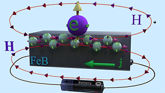
| There are two spin pumps. (spin pump 1): Localized d-electrons, which constantly creates spin-up conduction electrons. (spin pump 2): Due to Spin Hall effect, spin-left electrons is created. |
 |
| Big ball shows a large number of spin-polarized electrons of electron gas. The small balls shows direction of injected spin-polarized electrons from two spin pumps. |
| Spin direction of the front spin pump is toward left. Spin direction of the backside spin pump is toward up. |
| arrows shows the spin-direction and the volume of balls is proportional to the number of the spin polarized electrons |
| Details on Spin Torque are here |
| click on image to enlarge it |
The creation (origin) of the spin-orbit torque can be divided into two steps. At the first step, the spin-polarized electrons are created by an electrical current. At the second step, the created spin-polarized electrons affects the magnetic properties of the nanomagnet
The creation of the spin-polarized conduction electrons by an electrical current is called the Spin Hall effect (See here for details).
The major mechanism of creation of spin-polarized electrons is the spin-dependent scatterings (See Spin Hall effect for more details)
When there are spin-dependent scatterings, the spin-polarized electrons are accumulated at side edges of an electrical wire (Spin Hall effect). For example, if initially the conduction electrons are not spin-polarized, the probability of a scattering of a spin-up electron is larger to the left with respect to current direction and the probability of a scattering of a spin-down electron is larger to the right, then there are more spin-up electrons at the left side of wire and more spin-down electrons at the right side of the wire.
 Two sources of of generation of spin-polarized electrons:
The spin-polarization is created due to the spin-dependent scatterings across an interface. Typically spin-dependent scattering occurs at an interface between a non-magnetic heavy metal (like Pt, Ta, W) and ferromagnetic metal (like Fe,Co, FeCoB).
The spin-polarization is created due to the spin-dependent scatterings in the bulk of ferromagnetic metal. Typically the spin-dependent scattering occurs in a ferromagnetic metal containing a heavy metal (like FeBTb)
The SOT effect is usually observed in a ferromagnetic metal, where there are two groups of conduction electrons: (group 1) spin-unpolarized electrons and (group 2) spin-polarized electrons (see here). Correspondingly, there are two origins for creations of new spin-polarized electrons.
Two origins of generation of spin-polarized electrons: Due to spin-dependent scattering, some spin-unpolarized electrons becomes spin-polarized. The spin-polarization of these created spin-polarized electrons are different on opposite sides of the wire.
A spin-dependent scattering of already-existed spin-polarized electrons creates the spin-polarized electrons of different spin direction. As a result, there are two groups of spin-polarized electrons of different spin directions: (group 1) large group of "already-existed" spin-polarized electrons and (group 2) tiny group of "newly-created" of spin-polarized electrons. These two groups quickly interact with each other (See Spin Torque)
(influence 1) Spin torque
It is the case when the spin direction of "newly-created" spin-polarized electrons is different from the spin direction of "already-existed" spin-polarized electrons. In this case the Spin Torque is created. As a result, the spin direction of a large number of "already-existed" spin-polarized electrons rotates toward the spin-direction of a tiny number of "newly-created" spin-polarized electrons. This effect is called the Spin Torque.
Depending on the spin direction of "newly-created" spin-polarized electrons and the corresponded direction the Spin Torque., two torque torque can be distinguished: "damp-like" torque and "field-like" torque.
(influence 2) Change of size of nucleation domain for the magnetization switching
The electrical current induces the spin-transfer torque (it is the mechanism of the current induced magnetization reversal in a MTJ). Under influence of the spin-transfer torque, the domain wall of the nucleation domain for magnetization switching may may. As a result,
(influence 3) Change of the spin polarization
The electrical current creates the spin polarized electrons, which added to "already-existed" spin-polarized electrons. Depending on the polarity of the electrical current, the spin direction of "newly-created" spin-polarized electrons is either along or opposite to the spin direction of the "already-existed" spin-polarized electrons. As a result, the total spin polarization either decrease or increases for two opposite directions of the electrical current.
This influence makes current-dependent all magnetic properties, which depend on the spin polarization.
(influence 4) Change of the PMA energy
For a reason, which has not been understood yet, the PMA energy EPMA is changed by the electrical current. It leads to current-dependency of anisotropy field Hanis, coercive field Hc and delta Δ.

Non-existent "field- like" torque |
 |
| (fact): Field- like torque contradicts with the laws of Quantum mechanics |
| (fact): Field- like torque violates the important conservation law associated with the time-inverse symmetry |
| Click on image to enlarge it |
(Wrong path): In order to explain rather- complex measurement data of the 2nd harmonic method (see below) and the symmetrical & asymmetrical contributions to FMR resonance, the "damp-like" torque and the "field-like" torque wn order to explain the rather complex measurement data of the 2nd harmonic method and the symmetrical and asymmetrical contributions to FMR resonance, the introduction of two independent torques—the "damp-like" torque and the "field-like" torque—was made in violation of several conservation laws.

![]() (fact): Torque is a concept in classical mechanics used to describe the dynamics of interactions between objects. However, the torque concept does not have a direct counterpart in quantum mechanics.
(fact): Torque is a concept in classical mechanics used to describe the dynamics of interactions between objects. However, the torque concept does not have a direct counterpart in quantum mechanics.
![]() (fact): Quantum mechanics describe the dynamics of interactions between objects through transitions between quantum states. The spin dynamics, as a quantum phenomenon, is described by transitions between a lower energy spin-up quantum state and a higher energy spin-down quantum state. (see here)
(fact): Quantum mechanics describe the dynamics of interactions between objects through transitions between quantum states. The spin dynamics, as a quantum phenomenon, is described by transitions between a lower energy spin-up quantum state and a higher energy spin-down quantum state. (see here)

![]() (fact): The spin precession and the damping of the spin precession are intrinsic properties of the broken- symmetry.
(fact): The spin precession and the damping of the spin precession are intrinsic properties of the broken- symmetry.
![]() (warning): The introduction and prolonged use of the non-existent "field-like" torque underscore the limitations and risks associated with relying solely on torque-based descriptions of spin dynamics.
(warning): The introduction and prolonged use of the non-existent "field-like" torque underscore the limitations and risks associated with relying solely on torque-based descriptions of spin dynamics.
(The torque as a subject of the Classical Physics to resolve problem of Quantum Mechanic):
The torque is a subject of the Classical Mechanics describing how a force changes rotation of an object. The spin does not describe any rotation (See here). In the Quantum Mechanic, the orbital moment describes the object rotation (See here). The spin describes the properties of the broken time inverse symmetry, according to which the spin can either precess or align along or opposite to an external magnetic field. Any introduction of the classical torque should fit to the fundamental properties of the time inverse symmetry
 Violation of T- symmetry from the non- existing "field- like" torque
 (important note): The conservation of time-inversion symmetry, or T-symmetry, ranks among the most stringent conservation laws in our universe, akin in its stringency to the law of energy conservation.
![]() (T-symmetry and its conservation )
(T-symmetry and its conservation ) ![]() :
:
In nature, there exist reversible and irreversible processes, for which the T- symmetry is different. For instance, processes like light propagation along a path or spin precession are reversible, meaning that reversing the flow of time does not alter their behavior. Conversely, phenomena such as light absorption or spin damping are irreversible. Reversing the direction of time flow fundamentally changes the nature of these effects; for instance, light absorption becomes light amplification.
As a result, reversible processes are symmetrical against time reversal, while irreversible processes are asymmetrical.

as it reverses its polarity when time is reversed.
both magnetization M and electrical current reverse their polarity when time is reversed.
 The "field-like torque" violates T-symmetry
as it does not reverse its polarity when time is reversed.
both magnetization M and electrical current reverse their polarity when time is reversed.
This SOT effect is similar to the effect produced by an usual magnetic filed HDL , which is applied perpendicularly to the electrical current and perpendicularly to the magnetization.
The direction of the magnetic field HFL depends on the magnetization direction. When magnetization rotates along the z-axis. The magnetic field HDL rotates as well.
This SOT effect is similar to the effect produced by an usual magnetic filed HFL , which is applied along the electrical current.
The magnetic field HFL does not depend on the magnetization direction.
The bias current generates a spin-polarized electrons. The spin-polarized electrons at may affect the magnetization near film interface and consequently the the strength of the perpendicular magnetic anisotropy (PMA)
Change of magnetization switching time under current due to SOTdependence is opposite for spin-down to up and spin-down to up switching |
||||||
|
||||||
| The magnetization switching time at a different current density. Sample ud30 Volt53B Ta(2.5):FeCoB(1):MgO Nanowire width: 1000 nm, length 200 nm. Measurements date is 10. 2018 | ||||||
| Click on image to enlarge it |
Under a bias current, the hysteresis loop are shifted from its center position (See Fig). It looks similar as an additional magnetic field applied perpendicularly to the film.
The switching field from spin-up to down state became different from switching field from spin-down to up state
The Δ and retention time characterize stability of the magnetization against a thermally- activated reversal.
The modulation of the Δ changes the probability thermally-activated magnetization switching
The Meff is magnetization of first magnetic domain (nucleation domain), which triggers the magnetization reversal.
The bias current may move domain wall due to the spin-transfer torque. As a result the size of the nucleation domain becomes smaller or larger. Consequently, the Meff becomes smaller or larger.
The Hall angle or the Hall resistance depends on the magnetization of the ferromagnetic metal, spin-polarization of the conduction electrons and the strength of the spin-orbit (SO) interaction. The bias current generates a spin-polarized electrons. As a result, the spin polarization of electron gas and its distribution across film changes. It causes the change of the Hall angle.
"Damping-like" torque |
 |
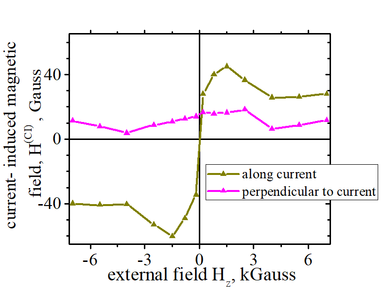
The electrical current creates a magnetic field HDL, which is directed along current and perpendicularly to the magnetization M.. Due to HDL, the magnetization M is inclined to the front direction. When external magnetic field Hext is applied, the magnetization M turns in-plane. Following M, HDL turns as well. From measurements of magnetization M vs Hext, HDL can be evaluated. |
| Click on image to enlarge it |
This SOT effect is similar to the effect produced by an usual magnetic filed HDL , which is applied perpendicularly to the electrical current and perpendicularly to the magnetization.
The "damping-like" torque is described as
where the effective magnetic field of the "damping-like" torque is defined as
![]()
Measurement method of "damping -like" torque HDL |
|||
|
|||
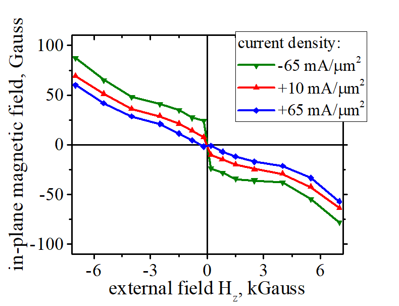
| Dependence of in-plane component of magnetization on in-plane plane magnetic field. The magnetic field is applied in-plane and perpendicularly to the current. The center of line is shifted, but its ends are at the same position. The HDL is the the offset magnetic field, which is proportional to the current. The HDL is evaluated by linear fitting of the dependence, which measured in Hall configuration. | |||
| Click on image to enlarge it |
It can be measured by the same measurement, which is used to measure the anisotropy field (See here). The in-plane component of magnetization is measured as a function of in-plane magnetic field. The in-plane magnetic field, which is applied perpendicularly to the electrical current.
The HDL gives the field offset for such measurement (See right Fig). From a linear fitting of measured dependence, the HDL is evaluated.
In the case of the "damp-like" torque the dependence M vs H is not linear. Even in the case the fitting gives a high precision.
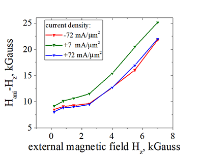
Effective magnetic field HDL of the "damping -like" torque |
|||||||||
|
|||||||||
| Measurements date is 10. 2018 | |||||||||
| Click on image to enlarge it |
"Field like" torque |
 |
| The electrical current creates a magnetic field HFL, which is directed along current. Due to HFL, the magnetization M is inclined to the right direction. When external magnetic field Hext is applied, the magnetization M turns fully in-plane at a smaller field Hext= Hanisotropy - HFL,in the left direction. The magnetization M turns field in-plane at a larger field Hext= Hanisotropy + HFL,in the right direction. Measuring the difference between two field, HFL can be evaluated |
| Click on image to enlarge it |
This SOT effect is similar to the effect produced by an usual magnetic filed HFL , which is applied along the electrical current.
The "field-like" torque is described as
where the effective magnetic field of the "field-like" torque is defined as
![]()
Measurement method of "field -like" torque HFL |
|||
|
|||
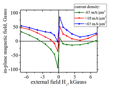
| Dependence of in-plane component of magnetization on in-plane plane magnetic field. The magnetic field is applied in-plane and along the current. HFL is the the offset magnetic field, which is proportional to the current. The HFL is evaluated by linear fitting of the dependence, which measured in Hall configuration. | |||
| Click on image to enlarge it |
It can be measured by the same measurement, which is used to measure the anisotropy field (See here). The in-plane component of magnetization is measured as a function of in-plane magnetic field. The in-plane magnetic field is applied along the electrical current.
The HFL gives the field offset for such measurement (See right Fig). From a linear fitting of measured dependence, the HFL is evaluated.
![]()
The dependence of HFL on the current is rather linear. All FeB and FeCoB samples, which I have measured by Nov. 2018, shows the same sign (positive) of HFL.
Effective magnetic field HFL of the "field like" torque induced by SOT |
|||||||||
|
|||||||||
| Measurements date is 10. 2018 | |||||||||
| Click on image to enlarge it |
Change of anisotropy field Hanis & PMA energy due to the SOT effect |
||||||||||||||||
|
||||||||||||||||
| Measurements date is 10. 2018 | ||||||||||||||||
| Click on image to enlarge it |
Measurement method of anisotropy field |
||
| Dependence of in-plane component of magnetization on in-plane plane magnetic field. The slope depends on the electrical current. The anisotropy field is evaluated from the slope of the line. | ||
| Click on image to enlarge it |
Change of coercive field due to the SOT effect (case 1:stronger heating) |
||||||
|
||||||
| Data was measured using method described here, which gives measurement precision of coercive field better than 0.1 Oe. | ||||||
| Sample Ta(5)/FeB(0.9)/ MgO(6)/ Ta(1)/Ru(5) (Volt55 free44). Measurements date is 06. 2018 | ||||||
| Click on image to enlarge it |
When current increases, two effects occur:
1.Heating
Even though the measurements of the coercive field are done in pulse mode, it is difficult completely avoid heating.
Due to the heating coercive field decreases. However, the decrease of the switching field between spin-down to up and switching field between spin-up to down states are absolutely identical and symmetrical (See here)
2. SOT effect
Change of coercive field due to the SOT effect (case 2: weaker heating) |
||||||
|
||||||
| Sample ud30 Volt53B Ta(2.5):FeCoB(1):MgO Nanowire width: 1000 nm, length 200 nm. | ||||||
| Click on image to enlarge it |
Sample distribution of ΔHc |
 |
| Measured sample distribution of the current- modulation of the coercive field ΔHc in FeB and FeCoB samples. |
| Click on image to enlarge it |
|
||||||
| Sample ud30 Volt53B Ta(2.5):FeCoB(1):MgO Nanowire width: 1000 nm, length 200 nm | ||||||
| Click on image to enlarge it |
modulation of effective size of nucleation domain |
||||
|---|---|---|---|---|
|
||||
| Dependence of size of nucleation domain on the electrical current. The black line shows for the case of magnetization switching from spin-down to spin-up state. The red line show for the case of switching from spin-up to spin-down state. | ||||
| Click on image to enlarge it |
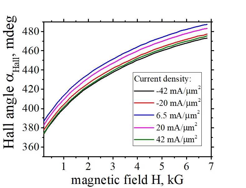
SOT modulation of Hall angle |
 |
| Difference of Hall for two opposite polarities of the bias current vs absolute value of current. The proximity of MgO modifies significantly |
| Sample: Ta(5):FeCoB ( 1 nm, x=0.3):MgO(7) Volt58A (L58B); nanowire width is 3000 nm, nanowire length is 25 um, length of um etched section is 3 um. For measurements of different magnetic properties of this sample click here |
| Click on image to enlarge it |
Dependence of spin polarization on polarity of bias current (SOT effect) |
||||||
|
||||||
click on image to enlarge it |
Experiment |
||
|
||
| Click on image to enlarge it. |
My Measurement Technique of current dependences of magnetic properties of ferromagnetic metal
All SOT measurements were done using the Anomalous Hall Effect (AHE).
![]() Fabrication of FeB, FeCoB and FeTbB nanomagnets connected to a Hall probe
Fabrication of FeB, FeCoB and FeTbB nanomagnets connected to a Hall probe
The FeB, FeCoB and FeTbB films were grown on a Si/SiO2 substrate by sputtering. A Ta layer was used as a non-magnetic adhesion layer. The thickness of the Ta was between 2 and 10 nanometers and wafers of different Ta thickness were tested. A nanowire of different width between 100 and 1000 nm with a Hall probe was fabricated by the argon milling. The width of the Hall probe is 50 nm. The FeB and FeCoB layers were etched out from top of the nanowire except a small region of the nanomagnet, which was aligned to the Hall probe. The nanomagnets of different lengths between 100 nm to 1000 nm were fabricated.
The SOT becomes substantial at the current of about 10-100 mA/um2. The heating of nanowire is substantial at this current. It is hard to remove the heating even when a pulse mode is used. For example, in my standard measurements an electrical pulse of 300 ms following 5 s cooling is used. However, there is still a substantial heating in this pulse mode (see below).
A. The SOT effect is linearly proportional to current, but heating ~I2, at a relatively-small current the SOT dominates, but at a higher current the heating dominates.
![]() 1) Sweep polarity of current
1) Sweep polarity of current
Usually (but not always) the SOT changes its polarity when the polarity of current is reversed. The heating does not dependent on the current polarity
![]() 2) use a narrower and shorter nanowire.
2) use a narrower and shorter nanowire.
The dissipation of heating is more effective in this case.
Effective magnetic field of "damp-like" and "anti damp-like" torque |
||||||
|
||||||
| Red arrow shows the spin (the magnetization). Blue arrow show the magnetic field Hext. Green arrow shows the effective magnetic field of the damp Hdamp (anti damp Hanti damp) torque. | ||||||
| Click on image to enlarge it |
![]() Properties of effective magnetic field of "damp-like" torque
Properties of effective magnetic field of "damp-like" torque
![]() Its direction changes, when the spin direction (magnetization direction) changes.
Its direction changes, when the spin direction (magnetization direction) changes.
![]() Its magnitude changes, when the spin direction (magnetization direction) changes. The magnitude is the largest, when the spin is perpendicular to Hext and the magnitude is the smallest (equals to 0), when the spin is parallel to Hext.
Its magnitude changes, when the spin direction (magnetization direction) changes. The magnitude is the largest, when the spin is perpendicular to Hext and the magnitude is the smallest (equals to 0), when the spin is parallel to Hext.
![]() What is the direction of the "damp-like" torque?
What is the direction of the "damp-like" torque?
3 components of the "damp-like" torque can be distinguished. They are labeled as Hdamp,x , Hdamp,y and Hdamp,z.
Since the direction and magnitude of the effective magnetic field of "damp-like" torque changes when the magnetization direction is changed, the following definition is used:
Hdamp,x aligns magnetization along the x-axis (along bias current)
Hdamp,y aligns magnetization along the y-axis. (in-plane and perpendicularly to bias current)
Hdamp,z aligns magnetization along the z-axis. (perpendicularly to plane)
Direction of effective magnetic field of "damp-like" torque |
||||||
|
||||||
Red Arrow :M is the magnetization (the spin). |
||||||
| Click on image to enlarge it |
![]() most probable direction of the "damp-like" torque is Hdamp,x
most probable direction of the "damp-like" torque is Hdamp,x
It is because of the following reason: The bias current breaks the time-reversal symmetry along the x-axis. Similarly, the time-reversal symmetry breaks in this direction, when a magnetic field is applied along the x-axis. Then, damp-like" torque is Hdamp,x aligns the magnetization along this field
Note: The existence of Hdamp,y and Hdamp,z is also allowed by the symmetry.
![]() How Hdamp,x , Hdamp,y and Hdamp,z change their magnitude and direction when magnetization is rotated in the yz-plane and the xz-plane
How Hdamp,x , Hdamp,y and Hdamp,z change their magnitude and direction when magnetization is rotated in the yz-plane and the xz-plane
![]() It is important because from measurements of such rotation both is "field-like" torque and "damp-like" torque are evaluated.
It is important because from measurements of such rotation both is "field-like" torque and "damp-like" torque are evaluated.
in short: 2nd harmonic method
Measurement method of 2nd harmonic. |
 |
In this method, the 2nd harmonic of the Hall voltage is measured while applying a modulated electron current. The electron current j (indicated by the red arrow) modulates the direction of magnetization. As the Hall voltage is directly proportional to both the electrical current and the perpendicular component of magnetization, the resulting frequency beating between these two modulated components gives rise to the 2nd harmonic of the Hall voltage. Consequently, the signal of the 2nd harmonic is proportional to the modulation of magnetization by an electrical current. |
| Click on image to enlarge it |
A low- frequency (50-500 Hz) AC voltage is applied at ends to a ferromagnetic wire and the second harmonic of the Hall voltage is measured by a lock-in amplifier.
 (answer:) Modulation of magnetization direction by an electrical current
The presence of the 2nd harmonic of the Hall voltage arises from proportionality of the Hall angle to both the electrical current and the perpendicular component of magnetization resulting in frequency beating those two modulated components.Therefore, the 2nd harmonic signal is directly proportional to the degree of magnetization modulation induced by the current.
There are at least five contributions to the 2nd harmonic signal, each of which can be independently and individually measured. The properties and behavior of each contribution are distinct and complex due to the diverse physics underlying each contribution
contribution 1 to 2nd harmonic signal: Magnetization precession |
||||||
| Why it contributes to 2nd harmonic signal: | ||||||
|---|---|---|---|---|---|---|
| A larger current makes the precession angle larger. It makes the perpendicular components of magnetization smaller. It makes the Hall angle smaller. | ||||||
|
||||||
| See more details about this measurement here and here | ||||||
| click on image to enlarge it |
![]() (reason why): The larger precession angle results in a smaller perpendicular component of magnetization.
(reason why): The larger precession angle results in a smaller perpendicular component of magnetization.
![]() (how to measure):
(how to measure):
method 1: measurement of RF oscillations (current- induced FMR).
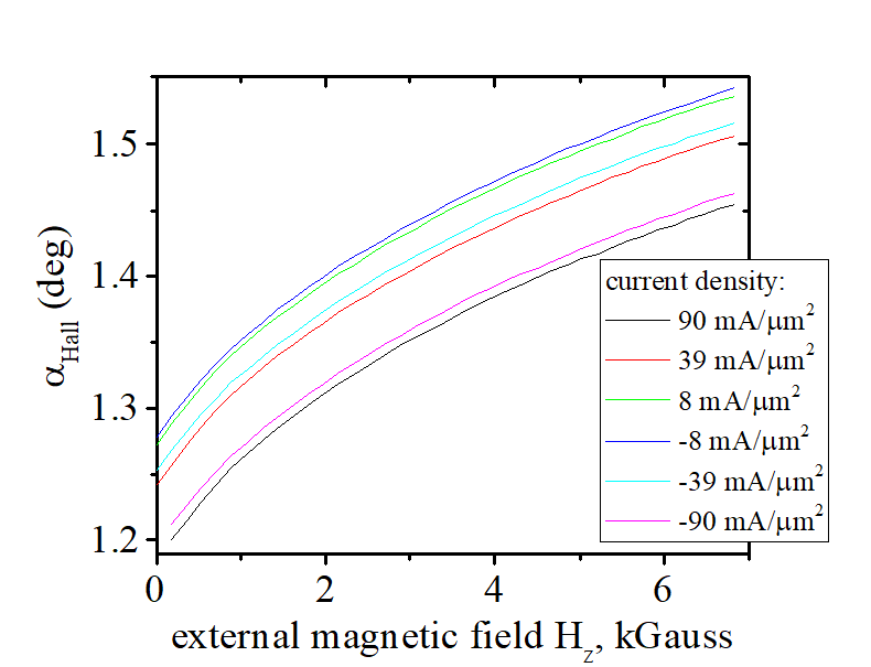
method 2: From current- dependence of Hall angle.
![]() (experimental fact): The measured Hall angle clearly reduces under a larger electrical current. This is because a larger current increases the precession angle, subsequently reducing the perpendicular components of magnetization, which in turn leads to a reduction in the Hall angle. (Right graph ). Therefore, this effect contributes to the data of the 2nd harmonic measurement.
(experimental fact): The measured Hall angle clearly reduces under a larger electrical current. This is because a larger current increases the precession angle, subsequently reducing the perpendicular components of magnetization, which in turn leads to a reduction in the Hall angle. (Right graph ). Therefore, this effect contributes to the data of the 2nd harmonic measurement.
![]() (reason why): Spin-polarized conduction electrons become accumulated at the edges of a metallic wire as a result of the Spin Hall effect when an electrical current passes through the wire. This accumulation generates a magnetic field attributed to the spins. The spins of these electrons, along with their magnetic field, lie in-plane and are perpendicular to the direction of magnetization. Consequently, the magnetic field induces a tilt in the magnetization towards the in-plane direction. Given that the level of spin accumulation correlates with the current, the degree of tilt is proportionate to the current, fulfilling the conditions necessary for contributing to the 2nd harmonic signal.
(reason why): Spin-polarized conduction electrons become accumulated at the edges of a metallic wire as a result of the Spin Hall effect when an electrical current passes through the wire. This accumulation generates a magnetic field attributed to the spins. The spins of these electrons, along with their magnetic field, lie in-plane and are perpendicular to the direction of magnetization. Consequently, the magnetic field induces a tilt in the magnetization towards the in-plane direction. Given that the level of spin accumulation correlates with the current, the degree of tilt is proportionate to the current, fulfilling the conditions necessary for contributing to the 2nd harmonic signal.
![]() (how to measure): The magnetic field generated by the spin accumulation can be reliably and precisely measured using the method described here, in this paper (here or here) and in this paper (here or here)
(how to measure): The magnetic field generated by the spin accumulation can be reliably and precisely measured using the method described here, in this paper (here or here) and in this paper (here or here)
![]() (additional data): The method measures and tracks the spin precession and alignment of these spin-polarized electrons towards the easy axis. See Fig. 1(c) in this paper (here or here)
(additional data): The method measures and tracks the spin precession and alignment of these spin-polarized electrons towards the easy axis. See Fig. 1(c) in this paper (here or here)
![]() (experimental fact): The measured in-plane magnetic field, which is created by spin accamulation, evidently varies with the electrical current. As the electrical current increases, the spin accumulation also increases. This larger spin accumulation results in a correspondingly larger in-plane magnetic field, which consequently tilts the magnetization at a greater angle. This tilting effect reduces the perpendicular components of magnetization and subsequently decreases the Hall angle. Therefore, this effect contributes to the data of the 2nd harmonic measurement.
(experimental fact): The measured in-plane magnetic field, which is created by spin accamulation, evidently varies with the electrical current. As the electrical current increases, the spin accumulation also increases. This larger spin accumulation results in a correspondingly larger in-plane magnetic field, which consequently tilts the magnetization at a greater angle. This tilting effect reduces the perpendicular components of magnetization and subsequently decreases the Hall angle. Therefore, this effect contributes to the data of the 2nd harmonic measurement.
![]() (Distinguished feature): How to recognize and distinguish the spin accumulation from other contributions:
(Distinguished feature): How to recognize and distinguish the spin accumulation from other contributions:
(undeniable fact): Distinguished feature of spin accumulation is the precession of its spin and alignment of its spin along the total magnetic field. Any contribution which does not have these features is not related to the spin accumulation.
contribution 2 to 2nd harmonic signal: magnetic field generated by spin-accumulated electrons |
|||||||||||||||
| Why it contributes to 2nd harmonic signal: | |||||||||||||||
|---|---|---|---|---|---|---|---|---|---|---|---|---|---|---|---|
| As electrical current increases, spin accumulation increases. This larger spin accumulation results in a correspondingly larger in-plane magnetic field, which consequently tilts the magnetization at a greater angle. It makes the perpendicular components of magnetization smaller. It makes the Hall angle smaller. | |||||||||||||||
|
|||||||||||||||
| click on image to enlarge it |
contribution 3 to 2nd harmonic signal: Oersted magnetic field created by electrical current |
||||||||||
| Why it contributes to 2nd harmonic signal: | ||||||||||
|---|---|---|---|---|---|---|---|---|---|---|
| The Oersted magnetic field is linearly proportional to the electrical current. When an electrical current flows under a nanomagnet, this field tilts the magnetization of the nanomagnet. As the current increases, a larger Oersted magnetic field makes the magnetization tilt larger and, therefore, the Hall angle smaller. | ||||||||||
|
||||||||||
| See more details about this measurement here and here | ||||||||||
| click on image to enlarge it |
![]() (reason why): The conventional Oersted magnetic field, which is created by an electrical current, circulates around a wire and tilts the magnetization. Given that a portion of the current passes beneath the nanomagnet via the non-magnetic metal, it affects the magnetization of the ferromagnetic metal.
(reason why): The conventional Oersted magnetic field, which is created by an electrical current, circulates around a wire and tilts the magnetization. Given that a portion of the current passes beneath the nanomagnet via the non-magnetic metal, it affects the magnetization of the ferromagnetic metal.
![]() (how to measure): The magnetic field generated by the spin accumulation can be reliably and precisely measured using the method in this paper (here or here) (the same measurement method as for contribution 2)
(how to measure): The magnetic field generated by the spin accumulation can be reliably and precisely measured using the method in this paper (here or here) (the same measurement method as for contribution 2)
![]() (reason why): When an external magnetic field is applied perpendicular to the easy axis (in the in-plane direction), the magnetization tilts towards the in-plane direction. The degree of tilting is directly proportional to the strength of the anisotropy field. Consequently, when the electrical current modulates the anisotropy field, it also modulates the tilt angle. Therefore, this mechanism contributes to the 2nd harmonic measurement.
(reason why): When an external magnetic field is applied perpendicular to the easy axis (in the in-plane direction), the magnetization tilts towards the in-plane direction. The degree of tilting is directly proportional to the strength of the anisotropy field. Consequently, when the electrical current modulates the anisotropy field, it also modulates the tilt angle. Therefore, this mechanism contributes to the 2nd harmonic measurement.
![]() (how to measure): The method for precise measurement of the anisotropy field is detailed here and here and here and in this paper. The modulation of the anisotropy field induced by an electrical current is indeed significant.
(how to measure): The method for precise measurement of the anisotropy field is detailed here and here and here and in this paper. The modulation of the anisotropy field induced by an electrical current is indeed significant.
 (mechanism): The anisotropy field is influenced by the spin-accumulated electrons, but in this case their spin direction is aligned along the easy axis (perpendicular- to- plane). Furthermore, the modulation of the spin-orbit interaction by the electrical current also contributes to the modulation of the anisotropy field.
![]() (additional data): This measurement method also enables a measurement of the strength of spin-orbit interaction and its modulation by the electrical current. See here and this paper
(additional data): This measurement method also enables a measurement of the strength of spin-orbit interaction and its modulation by the electrical current. See here and this paper
contribution 4 to 2nd harmonic signal: Modulation of anisotropy field |
|||||||||||||||||||||||||||||||
| Why it contributes to 2nd harmonic signal: | |||||||||||||||||||||||||||||||
|---|---|---|---|---|---|---|---|---|---|---|---|---|---|---|---|---|---|---|---|---|---|---|---|---|---|---|---|---|---|---|---|
| A larger current makes the precession angle larger. It makes the perpendicular components of magnetization smaller. It makes the Hall angle smaller. | |||||||||||||||||||||||||||||||
|
|||||||||||||||||||||||||||||||
| See more details about this measurement here and here and here | |||||||||||||||||||||||||||||||
| click on image to enlarge it |
contribution 5 to 2nd harmonic signal:modulation of amount of spin- polarized electrons |
||||||||
| Why it contributes to 2nd harmonic signal: | ||||||||
|---|---|---|---|---|---|---|---|---|
| A larger current makes the precession angle larger. It makes the perpendicular components of magnetization smaller. It makes the Hall angle smaller. | ||||||||
|
||||||||
| See more details about this measurement here and here | ||||||||
| click on image to enlarge it |
![]() (reason why): There are two primary contributions to the measured Hall voltage: the Anomalous Hall effect (AMR) and the Inverse Spin Hall effect (ISHE). The AMR accounts for the lateral deviation of the electrical current caused by the spins of localized electrons, whereas the ISHE involves the lateral deviation of the electrical current due to the spins of spin-polarized conduction electrons. As an electrical current alters the quantity of spin-polarized conduction electrons within a ferromagnetic metal, it modulates the ISHE and consequently the Hall angle. Therefore, this mechanism contributes to the 2nd harmonic measurement.
(reason why): There are two primary contributions to the measured Hall voltage: the Anomalous Hall effect (AMR) and the Inverse Spin Hall effect (ISHE). The AMR accounts for the lateral deviation of the electrical current caused by the spins of localized electrons, whereas the ISHE involves the lateral deviation of the electrical current due to the spins of spin-polarized conduction electrons. As an electrical current alters the quantity of spin-polarized conduction electrons within a ferromagnetic metal, it modulates the ISHE and consequently the Hall angle. Therefore, this mechanism contributes to the 2nd harmonic measurement.
![]() (how to measure): The spin polarization in a ferromagnetic nanomagnet is measured by the method described in this paper (here or here) or in this page and here. The modulation of spin polarization by an electrical current is substantial.
(how to measure): The spin polarization in a ferromagnetic nanomagnet is measured by the method described in this paper (here or here) or in this page and here. The modulation of spin polarization by an electrical current is substantial.
(mechanism): The conduction electrons in a ferromagnetic metal are spin- polarized even in the absence of an electrical current. However, when an electrical current is applied, it introduces additional spin-polarized electrons, which interact with the pre-existing spin-polarized electrons. Consequently, the average quantity of spin-polarized electrons becomes modulated by the electrical current.
(this is important) : It is evident that the simple single data from the 2nd harmonic alone cannot discern the contribution of each of these 5 intricate effects.
There are known measurement methods, which allow measurement of each contribution separately. It is imperative to use those measurement methods. Only then can the signal of the 2nd harmonic be accurately reconstructed and explained. Otherwise, all discussions on data of the 2nd harmonic measurement are very speculative.
![]() (why one should not use the 2nd harmonic method):
(why one should not use the 2nd harmonic method):![]()
I earnestly recommend utilizing those more reliable measurement techniques and reconstructing the 2nd harmonic signal independently. Doing so will lead to a clear realization of the limitations associated with 2nd harmonic measurements. I assure, once one has conducted such experiments, he/she will cease relying on 2nd harmonic measurements.
![]() (why one should not use the 2nd harmonic method):
(why one should not use the 2nd harmonic method):![]()
Continued reliance on the flawed and speculative interpretation of 2nd harmonic measurements could adversely affect the reputation of one's research. It is crucial to abandon this method in favor of more accurate approaches.The problems associated with 2nd harmonic measurements is a well-established fact known to many research groups.
No, the 2nd harmonic measurement is a valid and useful method. It measures a change in magnetization direction induced by an electrical current. However, its oversimplified interpretation of this measurement, which relies solely on simplified notions of "damp-like" and "field-like" torques, is incorrect. Rather, five complex mechanisms contribute to the measured 2nd harmonic signal. Additional measurements are necessary to distinguish and understand each of these contributions. Therefore, interpretations based solely on the 2nd harmonic measurement tend to be speculative and may not fully capture the underlying physics.
Absolutely not.
While the 2nd harmonic measurement does capture the contribution proportional to the angle of magnetization precession, and magnetization precession is induced by the torque and the precession angle is proportional to the strength of the torque, it also includes four additional contributions of similar, if not larger, magnitudes. Consequently, isolating the contribution directly proportional to magnetization precession from the 2nd harmonic signal is nearly impossible.
Absolutely not.
Regardless of the torque's origin, any torque acting on the magnetization results in an increase in the precession angle. A larger precession angle corresponds to a larger torque, irrespective of its origin. Even if it were feasible to isolate and quantify the current-induced change in the precession angle from the 2nd harmonic signal, distinguishing contributions from individual torques would be exceedingly challenging due to their identical effects on precession.
Furthermore, the application of an external magnetic field tilts the magnetization and complicates the precession, as described by the Kittel formula.
2nd harmonic measurement as a vivid example of hype and fake research.
| When future historians study the characteristics of how fake and hyped research is created, supported, and developed, the measurement of the 2nd harmonic could serve as an excellent example. It encapsulates all the known features of such misleading research. |
2nd harmonic measurement is an excellent example of a hyped and fake research, because it encapsulates all the known features of such misleading research.
 Known features of hype and fake research and their implications in 2nd harmonic measurements include:
 (feature 1 of hype and fake research): Fake research often originates from a genuine and accurate measurement, yet its interpretation is wholly incorrect. The incorrect interpretation is supported, because it allows constant reporting of mysterious and unexplainable results. Consequently, it facilitates numerous publications on the subject, inflates research indexes, and perpetuates a steady influx of government funding into such research topics.
(implementation in 2nd harmonic measurement): The 2nd harmonic measurement accurately evaluates the current-induced change in the perpendicular component of magnetization. The measurement itself is entirely correct. However, the provided explanation, which relies on the damp-like torque and field-like torque, is incorrect and absolutely unjustified.
(feature 2 of hype and fake research): The utilization of sophisticated terminology, fancy- sound names and terms, often bearing little or no correlation with the research topic, is a distinct feature of hype and fake research. These fancy words are employed to impress non-scientific individuals and bureaucratic figures within the scientific community, as well as to render the research topic more mysterious, unreachable and inaccessible to "simple" people.
(implementation in 2nd harmonic measurement): The terms "damp-like torque" and "field-like torque" are used for the incorrect explanation of the 2nd harmonic measurement. This flawed interpretation frequently leads to the discovery of purportedly new effects, distinguished only by their elaborate fancy names, which typically consist of combinations of words such as "spin," "torque," "current," "Hall," "enormous," "gigantic," and so on.
The existence of the field-like torque contradicts several conservation laws of quantum mechanics, rendering it a non-existent concept (see above). While the damp-like torque may have some applicability, it is not without limitations. Torque itself is not a subject of quantum mechanics; instead, quantum dynamics are typically described through quantum transitions. However, despite these limitations, the damp-like torque can still be employed within certain bounds.
(feature 3 of hype and fake research): Another distinguishing feature is that the majority of researchers are aware of the fraudulent nature of fake and hyped research. Despite this awareness, many researchers willingly acknowledge the existence of such deceptive studies and align their own interests with them. Simultaneously, there exists a correct explanation, supported by robust experimental and theoretical evidence. However, as long as the fraudulent research continues to yield benefits, it persists, often suppressing the correct explanation.
(implementation in 2nd harmonic measurement): A clear and straightforward correct explanation of the 2nd harmonic signal has been well-established since 2016. Direct measurements of each contribution to the 2nd harmonic signal have been documented in published papers and presented at top-rated conferences on Magnetism (such as MMM and Intermag). Despite the widespread awareness among researchers in the field regarding the fraudulent nature of the explanation rooted in "damp-like torque" and "field-like torque," publications and conference presentations based on this false interpretation continue to surface periodically up to the present day (2024).
(feature 4 of hype and fake research): Clear and understandable explanations pose the greatest threat to fake and hyped research. Such research deliberately avoids straightforward explanations at all costs. Instead, it employs tactics to evade the discussion of simple and easily understandable facts, while promoting complex, difficult-to-understand, and challenging-to-verify effects. These effects are often portrayed as well-known and self-evident, purportedly requiring no further explanation, justification, or proof.
(implementation in 2nd harmonic measurement): The faked interpretation of the 2nd harmonic measurement emphasizes that the 2nd harmonic data directly corresponds to the strength of the damp-like torque and field-like torque, presenting it as an indisputable fact beyond questioning or doubt. However, any specifics regarding why this is considered factual or what precisely constitutes the measured value corresponding to a torque remain elusive. Whether it pertains to the magnetic field utilized in torque descriptions within the Landau-Lifshitz equation, the angle of spin precession, or the alteration of anisotropy field (See more details here) , existing explanations are riddled with numerous complex and often incorrect details, seemingly designed to obfuscate rather than clarify the matter.
(feature 5 of hype and fake research): Usage of circle citation. Circular citation is a notable characteristic of fake research, employed to obscure a straightforward explanation. When the necessity for an explanation becomes unavoidable, citations are utilized, suggesting that the comprehensive explanation can be found in the referenced paper. However, upon scrutiny of the cited paper, it often diverges slightly from the previous topic, lacking the required explanation. Instead, it refers to yet another paper, which may be even more detached from the original subject. Consequently, the needed explanation remains elusive, seemingly resolved only through a chain of referenced papers.
(implementation in 2nd harmonic measurement): The circle citation is very popular in this fake research. The circle citation is often used when it is necessary to provide a simple sentence or two to justify the use of a specific formula or the discovery of a purportedly "new" torque or spin effect. Instead a citation to an article that supposedly explains everything is used. However, upon inspection of the cited article, one often finds either a tangential mention of the claim without substantive proof or a further citation, perpetuating the cycle of vague references.
(feature 6 of hype and fake research): Giving unrealistic promises, which nobody intends to keep. A significant portion of any presentation or paper related to fake and hyped research comprises numerous unrealistic promises, which nobody actually intends to fulfill. These often include science-fiction-like narratives, akin to Star Wars tales, depicting how the purported "fake research" will revolutionize the human race. These narratives typically lack any form of scientific evidence or justification. Moreover, the projected timelines for the realization of these promises are often exceedingly distant, spanning millions of years, rendering them effectively unverifiable. The primary target audience for such promises is often science bureaucrats whose scientific understanding is drawn largely from movies like Star Wars and similar science fiction films. These individuals are easily swayed by fantastical claims and seldom demand scientific justifications for such science fiction promises.
(implementation in 2nd harmonic measurement): Any presentation or paper on this fake topic often makes promises of delivering a super memory with an exceptionally efficient recording mechanism, purportedly due to the utilization of super-effective field-like torque or damp-like torque. However, in reality, the measured data of the 2nd harmonic bears only a distant relation to the effectiveness of data recording in a magnetic memory.
Measurement of "damp-like" torque and "field-like" torque by 2d harmonic lock-in technique |
||||||||
|
||||||||
| In this method the 2d harmonic of Hall voltage is measured as a function of an in-plane magnetic field | ||||||||
| Click on image to enlarge it |
(2nd harmonic measurement):
The Hall voltage is proportional to the current and the perpendicular components of magnetization. When current is modulated with frequency ω, the magnetization direction, the magnetization magnitude and spin-polarization of the conduction electrons are modulatedby a current at the same frequency ω. Due to the frequency beating , the Hall voltage is modulated with frequency 2ω. As a result, he 2d harmonic signal is linearly proportional to the magnetization direction, magnitude, and spin polarization of the conduction electrons
It has been commonly accepted, albeit inaccurately, that the "damp-like" torque and "field-like" torque can be measured and distinguished from each other through the following techniques:
(technique 1): The 2nd harmonic-lock-in technique;
(technique 2): From ST-FMR measurements.
Difference between "Damp-like" torque and "Field-like" torque |
|||||||||
|
|||||||||
| Click on image to enlarge it |
(main (incorrect) idea behind used separation method): dependence & independence on magnetization reversal
There are only two existing torques, and their dependence on the magnetization direction differs significantly. This feature is used to separate them.
One type of torque does not depend on the magnetization direction of the ferromagnetic metal. It is only depend on the direction of the current. Such torque is called the field-like torque.
The second type of torque does depend on the magnetization direction of the ferromagnetic metal. Such torque is called the damp-like torque.
![]() field-like torque
field-like torque
1.It does not depend on the magnetization direction of the ferromagnetic metal.
2. The magnetic field HFL of the "field-like" torque is oriented along the current , meaning it lies in the in-plane direction along to the current.
![]() damp-like torque
damp-like torque
1.It does depend on the magnetization direction of the ferromagnetic metal.
2. The magnetic field HDL of the "damp-like" torque lies in the in-plane direction perpendicular to the current.
![]() 1. "Field-like" torque
1. "Field-like" torque
It can be evaluated from the symmetric component of dependence of the 2d-harmonic voltage vs the in-plane magnetic field, when the magnetic field is applied along the current.
![]() 2. "Damp-like" torque
2. "Damp-like" torque
It can be evaluated from the asymmetric component of dependence of the 2d-harmonic voltage vs the in-plane magnetic field, when the magnetic field is applied perpendicularly the current.

Both the "damp-like" torque and "field-like" torque are associated with corresponding magnetic fields HDL and HFL, both of which are linearly proportional to the electrical current j.
![]() (fact): The electrical current indeed generates a magnetic field, comprising three components that can be measured with high precision (see here). The first component is the conventional Oersted field, which circulates around the current. The second component is the magnetic field created by the spins of the spin-accumulated electrons. The third is related to magnetization. However, these magnetic fields do not produce any torque except when the conditions of the parametric resonance are satisfied.
(fact): The electrical current indeed generates a magnetic field, comprising three components that can be measured with high precision (see here). The first component is the conventional Oersted field, which circulates around the current. The second component is the magnetic field created by the spins of the spin-accumulated electrons. The third is related to magnetization. However, these magnetic fields do not produce any torque except when the conditions of the parametric resonance are satisfied.

 Math of "damp-like" torque:
The "damp-like" torque is described as
where the effective magnetic field HDL of the "damp-like" torque is defined as
![]()
![]() (direction): The magnetic field HDL of the "damp-like" torque is oriented perpendicular to both the current and the magnetization, meaning it lies in the in-plane direction perpendicular to the current.
(direction): The magnetic field HDL of the "damp-like" torque is oriented perpendicular to both the current and the magnetization, meaning it lies in the in-plane direction perpendicular to the current.
 (symmetry): The polarity of the magnetic field HDL of the "damp-like" torque reverses when the magnetization is reversed.
Math of "field-like" torque:
The "field-like" torque is described as
where the effective magnetic field HFL of the "field-like" torque is defined as
![]()
![]() (direction): The magnetic field HFL of the "field-like" torque is oriented along the current , meaning it lies in the in-plane direction along to the current.
(direction): The magnetic field HFL of the "field-like" torque is oriented along the current , meaning it lies in the in-plane direction along to the current.
(symmetry): The polarity of the magnetic field HFL of the "field-like" torque does not change when the magnetization is reversed.
Results:
The fields of the the spin-orbit torque can be calculated from the following dependance of the 2d-harmonic voltage VHall,2ω vs applied in-plane magnetic field Hx :

where ΔHanis,ω is the current induced change of the anisotropy field Hanis; ΔHoff,ω is the effective magnetic field HFL,ω of the "field-like" torque, when Hx is applied along electrical current; and ΔHoff,ω is the effective magnetic field HDL,ω of the "damp-like" torque, when Hx is perpendicularly to the electrical current;
the odd and even components can be calculated as
Rwire is the is the ohmic resistance of the wire; RHall,0 is the is the Hall resistance, when a in-plane magnetic field is not applied ;
Hanisot is the anisotropy field, which can be measured directly (See here) with a high precision or from 1st harmonic with a moderate precision.
The Hanisot can be evaluated from the following dependance of the 1d-harmonic voltage VHall,ω vs applied in-plane magnetic field Hx :
Without electrical current, the in-plane component of the magnetization Mx depends on the applied external in-plane magnetic field Hx as (see here)
where Hanis is the anisotropy field
As was demonstrated above, the spin-orbit torque (SOT) produces the offset magnetic field ΔHoff and changes the anisotropy field Hanis on ΔHanis. As a result, the Eq.(4.1) is modified as
![]()
where ΔHoff equals to HFL when the in-plane magnetic field is applied along current and ΔHoff equals to HDL when the in-plane magnetic field is applied in-plane and perpendicularly to the current
In the case when
![]()
Eq.(4.2) can be simplified as
or 
where 
from (4.2) we have ![]() .
.
The z- component of the magnetization Mz can be calculated as
or
The Hall voltage is calculated as
![]()
when magnetization is not perpendicular to plane, the Hall voltage is calculated as
![]()
where Mz is the perpendicular-to-film component of magnetization, RHall,0 is the Hall resistance when the magnetization is perpendicular to the film (Mz =M).
When the current is modulated with frequency ω ,
![]()
both the ΔHoff and ΔHanis are modulated as well:
![]()
Using a trigonometric relation
and substituting Eqs (4.7) (4.10),(4.11) into Eqs. (4.7) gives the Hall voltage VHall,2ω of the 2d harmonic (the coefficient at cos(2ωt)) as

In a lock-in measurement it is convenient to use the reference voltage Vω rather than reference current Iω
2d harmonic |
 |
| as a function of applied in-plane magnetic field. |
| Click on image to enlarge it |
where Rwire is the resistance of metallic nanowire.
Substituting Eqs. (4.2) and (4.14) into Eq. (4.13) gives
or

The voltage of the second harmonic has two component. The first component is proportional to ΔHoff and is an odd function in the respect to Hx. The first component is proportional to ΔHanis and is an even function in the respect to Hx. Therefore, the voltage of the second harmonic can be calculated as
2d harmonic |
 |
| as a function of applied in-plane magnetic field. |
| Click on image to enlarge it |
Eq (4.17) can be written in a symmetrical form as
where
1st harmonic |
 |
| Perpendicular-to-plane component of magnetization as a function of applied in-plane magnetic field. |
| Click on image to enlarge it |
When current is small, the ΔHoff and ΔHanis can be ignored. Than, the Hall voltage VHall,ω of 1st harmonic can be calculated from Eq.(4.9) as
![]()
substitution of Eq(4.1) into Eq.(4.20) gives the Hall voltage VHall,ω of 1st harmonic as
The ratio of voltage of 1st harmonic to the voltage of 1st harmonic can be calculated as
Measurement of anisotropy field Hanis |
||
|
||
| The arrow shows the direction and magnitude of the applied in-plane magnetic field. The ball shows the magnetization direction. Without magnetic field the magnetization is perpendicularly-to-plane. Under magnetic field, the magnetization turns toward magnetic field. The field, at which the magnetization turns completely in-plane, is called the anisotropy field. The dots of the right graph shows experimental data. Measurement date: May 2018. | ||
| Click on image to enlarge it |
Electrical current can induce spin torque or reduce the exchange interaction between localized electrons. This can change the direction of magnetization of a material.
Current-induced magnetization reversal in FeBTb film
|
||||
|
Two current-induced effects, which can lead to the current-induced magnetization reversal:
Both effects occur because of transfer of delocalized (conduction) spin-polarized electrons from a point to point, which alters an equilibrium spin polarization in a material.
The spin torque occurs when the delocalized spin-polarized electrons are transferred from one material to another by a drift or a diffusion current. When spin-polarized delocalized electrons are injected, it is not only change magnitude of spin accumulation, but also it changes spin direction of spin accumulated electrons. As result, the spin direction of localized and delocalized electrons becomes different. This induces the torque, which may turn or reverse the spin direction of the localized electrons.
Note: At one place an electron gas may have only one spin direction of its spin accumulation. In the case when the electrons with a different spin direction is injected, the spins quickly relax and the spin accumulation of only one spin direction remains. The final spin direction is different from initial spin direction and from the injected spin direction. Details see here and here
The spin torque may change magnetization direction in a material because of the exchange interaction between localized and delocalized electrons.
There are several effects which can cause the current-induced spin torque:
1)The spin-transfer torque.
It occurs because of transfer of spin-polarized electron from material to material by a drift or diffusive spin current. Example: the spin transfer between electrodes in a MTJ or GMR junction. The polarity of the spin-transfer torque depends on mutual magnetization directions of the electrons.
2) The spin-orbit (SO) torque.
It occurs in magnetic or non-magnetic metals in which there are substantial spin-dependent scatterings. Due to spin-dependent scatterings a spin-polarized current flows perpendicularly to the flow of spin- unpolarized drift current. The spin is accumulated at one side of a metallic wire and the spin is depleted at another side. The spin accumulation(depletion) may cause the spin torque at sides of the wire, which magnitude and direction is proportional to the drift current. The accumulated spin may have different spin direction than the spin direction of the equilibrium spin polarization.
Current-induced magnetization reversal in FeBTb film
|
||||
|
Current-induced magnetization reversal in FeBTb film
|
||||
|
(about necessity to apply an in-plane magnetic field to achieve magnetization reversal)
(2024/04/26). There are several reasons why the application of an in-plane magnetic field (Hx) is necessary for achieving magnetization reversal, and these reasons depend on the specifics of the utilized magnetization reversal mechanism:
(magnetization reversal method 1) parametric magnetization reversal
This mechanism, functioning as a resonance mechanism, is highly effective and occurs at minimal current levels. However, it requires precise tuning and is only applicable in structures with magneto-resistance (MR). A larger MR is preferable, although even a small MR, such as AMR, can suffice for this resonance-based reversal. The key mechanism employed in parametric reversal involves the modulation of magnetization direction by electrical current. Whether Hx is required or not depends on the specific mechanism employed:
![]() (Mechanism 1): In-plane magnetic field H|| generated by spin accumulation due to the Spin Hall effect.
(Mechanism 1): In-plane magnetic field H|| generated by spin accumulation due to the Spin Hall effect.
Hx is not necessary here because H|| is perpendicular to magnetization M and tilts the magnetization.
![]() (Mechanism 2): Modulation of anisotropy field Hani by current.
(Mechanism 2): Modulation of anisotropy field Hani by current.
Hx is required in this case. In equilibrium, the magnetization aligns along the easy axis, and modulation of Hani does not tilt M. The application of Hx, however, tilts M, with the tilting angle dependent on Hani . Therefore, modulation of Hani results in a modulation of the magnetization tilting angle. See more here:
(magnetization reversal method 2) conventional reversal by an injection of a large amount of spins
![]() (Case 1): Injected spin is opposite to magnetization.
(Case 1): Injected spin is opposite to magnetization.
Hx is not required.
![]() (Case 2): Injected spin is perpendicular to magnetization.
(Case 2): Injected spin is perpendicular to magnetization.
Hx is required.
This scenario is applicable to nanomagnets with perpendicular magnetic anisotropy (PMA), where the injected spin direction is in-plane, as generated by the Spin Hall effect.
 ( about magnetic domains)
Regarding magnetic domains, it's important to note the distinction between static domains and nucleation domains. Nucleation domains are transient, unstable and exist briefly during magnetization reversal. In my studies of FeCoB nanomagnets ranging from 30 nm x 30 nm to 3000 nm x 3000 nm, static domains are rare. Nucleation domain sizes range from 30 nm to 80 nm, depending on nanomagnet quality. Measuring nucleation domain size is a relatively simple and well-established technique, detailed in this Web page
Under Hx, the size of the nucleation domain decreases rapidly, leading to a decrease in coercive field HC and facilitating thermal-activated magnetization reversal. However, Hx also reduces overall thermal stability due to reduced nucleation domain size, making this method somewhat tricky.
Hx affects nucleation domain wall movement speed, impacting the speed but not the efficiency of magnetization reversal.
Your answer does not have a simple and short answer. In general, symmetry is important. In reality, the necessity or unnecessity of applying Hx for magnetization reversal depends largely on sample properties and the specific magnetization reversal mechanism employed.
(about systematic errors of 2nd harmonic measurements)
![]() Regarding 2nd harmonic method, I have to disagree with you. The technic is reliable if you manipulate it correctly, and like any experiment there is always the risk of an “artifact” effect not taken into account. I believe that we have reached today a conclusion on how to perform an analysis using 2nd harmonic and to take into account spurious effects..
Regarding 2nd harmonic method, I have to disagree with you. The technic is reliable if you manipulate it correctly, and like any experiment there is always the risk of an “artifact” effect not taken into account. I believe that we have reached today a conclusion on how to perform an analysis using 2nd harmonic and to take into account spurious effects..
The problem of the 2nd harmonic measurement is that it has too many independent contributions, such as
1. magnetization precession due to spin injection
2. magnetic field Hoff, which is induced by the spin accumulation
3. Current dependency of anisotropy field
4. PHE/AMR effect.
Three of them can be used for magnetization reversal by an electrical current.
The fact is that the 2nd harmonic measurement does not have enough data to describe its own measured data, because of a large number of different independent contributions. The new method, which I have developed, measures each contribution individually and independently of other contributions. Each contribution has a rich and interesting Physics, which can be individually optimized for an efficient magnetization reversal.
--------------------------------
The 2nd harmonic measurement has the similar tendency as the current dependency of the magnetic field Hoff, which is induced by the spin accumulation. Therefore, it is OK to use data of the 2nd harmonic measurement in a publication, in which different tendencies are studied and discussed, and in which some systematic error is not a big issue. However, for a technology optimization, the use of a direct and more reliable measurement is better.
![]() (about field- like torque) (from Sreyas Satheesh) I had some serious doubts regarding the field like torque terms. You had mentioned the field-like field to be independent of the magnetization direction and to be directed along the direction of the current. However, in some of the works, I had found it to be orthogonal to the direction of the current. Ref: 1)Garello, K. et al. Symmetry and magnitude of spin-orbit torques in ferromagnetic heterostructures. Nature Nanotech. 8, 587–593 (2013). 2)Miron, I. M. et al. Perpendicular switching of a single ferromagnetic layer induced by in-plane current injection. Nature 476, 189–193 (2011).
(about field- like torque) (from Sreyas Satheesh) I had some serious doubts regarding the field like torque terms. You had mentioned the field-like field to be independent of the magnetization direction and to be directed along the direction of the current. However, in some of the works, I had found it to be orthogonal to the direction of the current. Ref: 1)Garello, K. et al. Symmetry and magnitude of spin-orbit torques in ferromagnetic heterostructures. Nature Nanotech. 8, 587–593 (2013). 2)Miron, I. M. et al. Perpendicular switching of a single ferromagnetic layer induced by in-plane current injection. Nature 476, 189–193 (2011).
(about torque & spin dynamic & Quantum mechanic)
There is only one torque, which is damping (or anti damping torque) of the Landau-Lifshitz equation. The introduction of any possible torque of different types or a different direction violates the rules of the Quantum Mechanics.
The spin is a pure quantum- mechanical object and the torque is the object of classical physics. Therefore, strictly-speaking it is incorrect to use the torque for a description of the spin dynamics. However, it is still possible to use the torque for the spin dynamics, when the torque closely mimics and well- approximates all features of the quantum-mechanical dynamics of the spin. The reason for the use of the torque is to simplify the description and understanding of the spin dynamics. However, in contrast to the classic mechanic, in which the torque may have any direction and magnitude, the quantum- mechanical rules limit the torque to only one possible direction and make the torque strength dependent on the spin precession angle.
The spin dynamics, as any quantum mechanical process, is described by a transition between quantum levels. In the case of the spin, the lower-energy level corresponds to spin direction along the magnetic field (spin-up) and the lower-energy level corresponds to spin direction opposite to the magnetic field (spin-down) . Only possible other quantum states of the spin are the states, whose energy is between the spin-up and spin-down levels and which corresponds to the spin precession at a different spin precession angle.
For example, in an equilibrium the spin is in the spun-up state and there is no spin precession. When there is an injection of spin-down electrons, both the spin-up and spin-down quantum states are partially filled, which corresponds to the spin precession. The spin precession is larger when there are more spin-down electrons. This quantum mechanical process can be described rather well and reasonably correctly by the damping torque (or anti-damping torque) of the Landau-Lifshitz (LL) equation.
Except for the transition between the spin-up and spin-down quantum levels, which is described by the damping torque of LL Eqs, I do not see any other options for a possible quantum spin dynamic and, therefore, any possibility for introduction of the other torque. For example, another possible mechanism of the spin reversal, the parametric magnetization reversal, when the magnetization direction is modulated in the resonance with spin precession, is also described by the transition between the spin-up and spin-down quantum levels and, therefore, the same anti-damping torque of LL Eqs. You can find more explanations about this in this video (click here)
There is no such thing as the field-like torque. However, there is a magnetic field, which is induced by spin-accumulated electrons. Since the spin accumulation is created by the current, this magnetic field can be modulated by current and can be used for the parametric magnetization reversal. One of the in-plane components of this magnetic field is incorrectly associated with the damp-like torque and another in-plane component is incorrectly associated with the field-like torque. The reason for that is the symmetry of the 2nd harmonic measurement with respect to the magnetization reversal. More details about this magnetic field and its measurement you can find in this video (click here).
Two papers, which you have mentioned, are two important papers, in which the field-like torque was introduced based on the 2nd harmonic measurement. However, the problem of the 2nd harmonic measurement is that it is influenced by too many parameters and the data of measurement of the 2nd harmonic alone is not sufficient to explain the changes of all those parameters. Now the direct measurements have clarified the situation. You can find the explanation about it in the mentioned video.
In the two mentioned papers, the puzzling data of the 2nd harmonic measurement was explained by the introduction of the field-like torque. It is a great, but incorrect idea. It is a very natural way of the development of science. Some great, but incorrect models may exist until new data clarifies the situation.
 Video
Video 
Parametric magnetization reversal. Spin- orbit torque Conference presentation. Intermag 2021 |
|---|
|
Measurement of coefficient of spin- orbit interaction, anisotropy field in a nanomagnet and magnetic field created by a spin accumulation.
|
|||||||||||||||||||||||||||||||||||
|---|---|---|---|---|---|---|---|---|---|---|---|---|---|---|---|---|---|---|---|---|---|---|---|---|---|---|---|---|---|---|---|---|---|---|---|
| click on image to play it |
![]()
![]() I am strongly against a fake and "highlight" research
I am strongly against a fake and "highlight" research ![]()
![]()
![]()
![]()
![]()
![]()
I will try to answer your questions as soon as possible


 Parametric reversal
 thermally-activated reversal
  mechanisms of magnetization reversal by an electrical current (SOT effect)
 Mechanisms of creation of Spin accumulation by an electrical current