Dr. Vadym Zayets
v.zayets(at)gmail.com
My Research and Inventions
click here to see all content |

Dr. Vadym Zayetsv.zayets(at)gmail.com |
|
|
more Chapters on this topic:IntroductionTransport Eqs.Spin Proximity/ Spin InjectionSpin DetectionBoltzmann Eqs.Band currentScattering currentMean-free pathCurrent near InterfaceOrdinary Hall effectAnomalous Hall effect, AMR effectSpin-Orbit interactionSpin Hall effectNon-local Spin DetectionLandau -Lifshitz equationExchange interactionsp-d exchange interactionCoercive fieldPerpendicular magnetic anisotropy (PMA)Voltage- controlled magnetism (VCMA effect)All-metal transistorSpin-orbit torque (SO torque)What is a hole?spin polarizationCharge accumulationMgO-based MTJMagneto-opticsSpin vs Orbital momentWhat is the Spin?model comparisonQuestions & AnswersEB nanotechnologyReticle 11
|
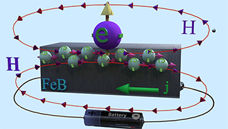
Measurement of Spin-orbit - type in- plane magnetic field: " field- like torque" + "damp- like torque" Spin and Charge TransportAbstract:There is an intrinsic magnetic field with a nanomagnet with Perpendicular Magnetic Anisotropy. Its direction and magnitude is changed under applied external perpendicular magnetic field and under electrical current. Since this field influences the probability of the magnetization reversal, it is often called the "field- like torque" or "damp- like torque".
|
| In-plane magnetic field induced by spin- accamulation created by current | ||||||
|---|---|---|---|---|---|---|
|
||||||
| Blue ball shows the magnetization. Green balls show the spin accamulation | ||||||
| click on image to enlarge it |
|
||
(fact ) ![]() A nanomagnet with the Perpendicular Magnetic Anisotropy (PMA) has in-plane magnetic field H||, which is about 30-50 Gauss without an external magnetic field.
A nanomagnet with the Perpendicular Magnetic Anisotropy (PMA) has in-plane magnetic field H||, which is about 30-50 Gauss without an external magnetic field.
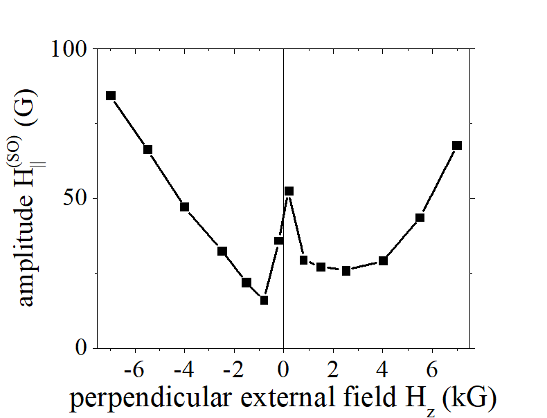
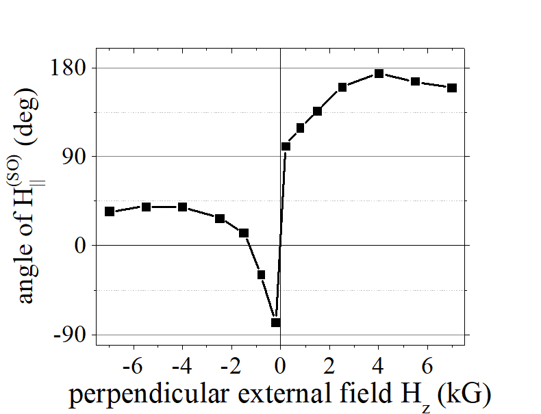
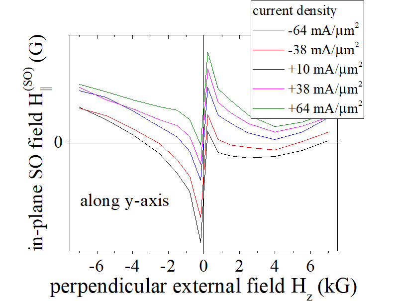
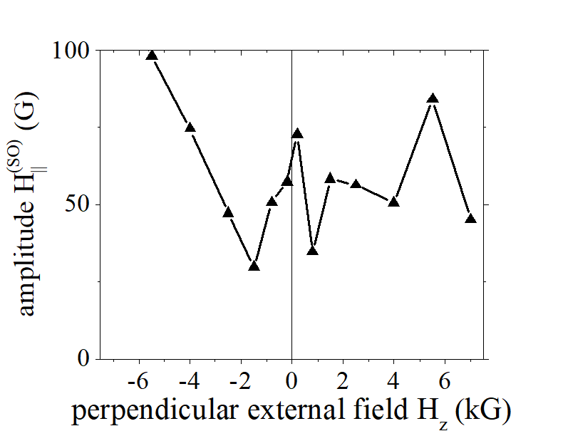
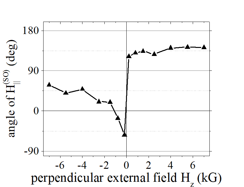
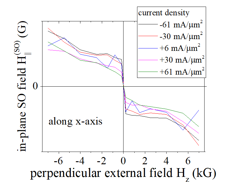
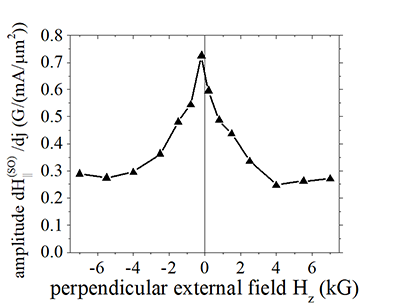
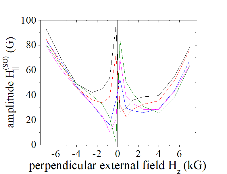
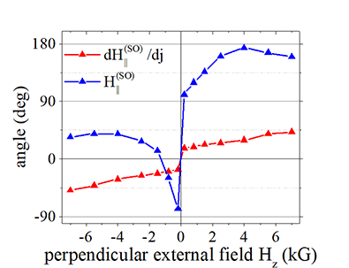
(fact: origin ) ![]() The origin of this in-plane field is the spin-orbit interaction (SO) and the origin is similar to the origin of PMA. This fact can be concluded from linear increase of the in-plane magnetic field under a large perpendicular magnetic field Hz (See Fig.1c below). Such dependence is very similar to the dependence of the anisotropy field on an external magnetic field (See here). Similarly, there is an oscillating feature for Hz<2 kG. The H|| reaches about 100 Gauss under external magnetic field Hz= 7 kGauss
The origin of this in-plane field is the spin-orbit interaction (SO) and the origin is similar to the origin of PMA. This fact can be concluded from linear increase of the in-plane magnetic field under a large perpendicular magnetic field Hz (See Fig.1c below). Such dependence is very similar to the dependence of the anisotropy field on an external magnetic field (See here). Similarly, there is an oscillating feature for Hz<2 kG. The H|| reaches about 100 Gauss under external magnetic field Hz= 7 kGauss
(fact: discontinuity at Hz =0) ![]() The in-plane magnetic field H|| sharply changes its magnitude and direction at Hz =0.
The in-plane magnetic field H|| sharply changes its magnitude and direction at Hz =0.
(fact: dependence on demagnetization field) ![]() The in-plane magnetic field H|| depends on shape and sizes of the nanomagnet, which implies that the H|| depends on the demagnetization magnetic field.
The in-plane magnetic field H|| depends on shape and sizes of the nanomagnet, which implies that the H|| depends on the demagnetization magnetic field.
(fact: interfacial origin ) ![]() The in-plane magnetic field H|| depends substantially on polarity of external magnetic field . Such polarity non-symmetry can be created by a geometrical non- symmetry. There is only one non- symmetry of the measured nanomagnet: different materials at top and bottom interfaces. It implies the in-plane magnetic field H|| is created at the interfaces (similar to PMA)
The in-plane magnetic field H|| depends substantially on polarity of external magnetic field . Such polarity non-symmetry can be created by a geometrical non- symmetry. There is only one non- symmetry of the measured nanomagnet: different materials at top and bottom interfaces. It implies the in-plane magnetic field H|| is created at the interfaces (similar to PMA)
Measurement of SO in-plane magnetic field H||. Dependence on an external magnetic field Hz |
In-plane spin-orbit magnetic field H|| vs. external perpendicular magnetic field Hz. |
| sample Volt 54a nanomagnet R42C. Size 3000nm x 3000nm. See more details about sample here. |
| Click on image to enlarge it |

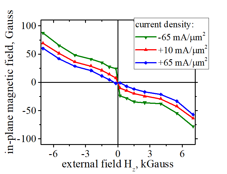
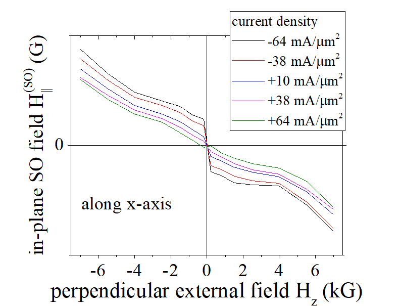
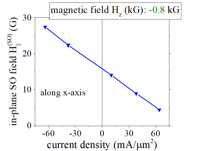
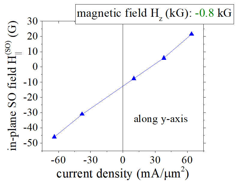
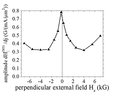
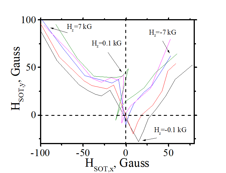
(fact ) ![]() There is an in-plane magnetic field H||, in a nanomagnet, which is linearly proportional to the electron current flowing in a nanomagnet. At current density of 100 mA/ μm2 (a very high density), the in-plane current- dependent SO field is about 40-70 Gauss
There is an in-plane magnetic field H||, in a nanomagnet, which is linearly proportional to the electron current flowing in a nanomagnet. At current density of 100 mA/ μm2 (a very high density), the in-plane current- dependent SO field is about 40-70 Gauss
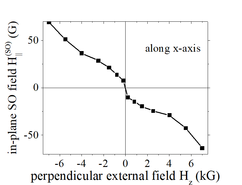
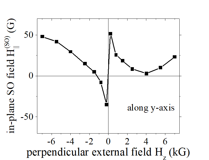
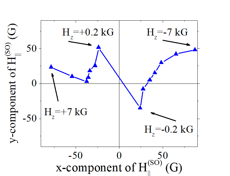
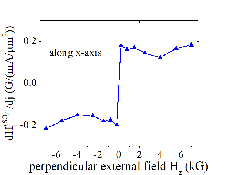
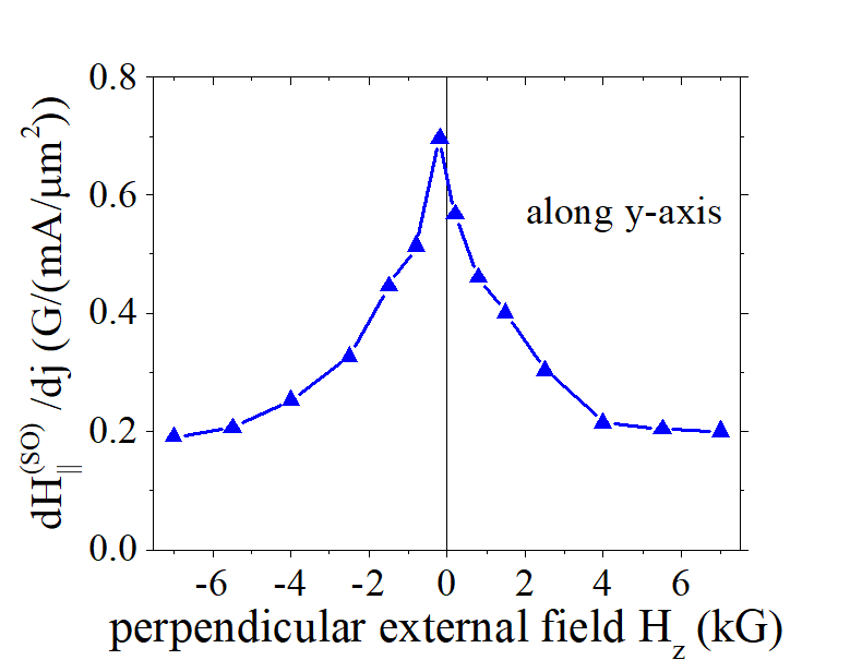
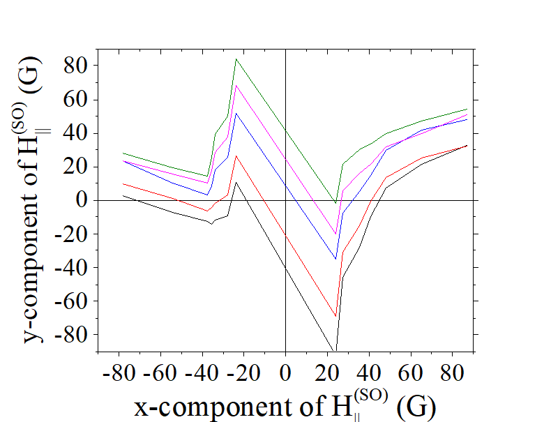
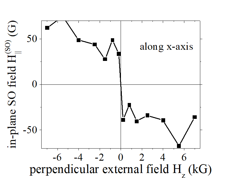
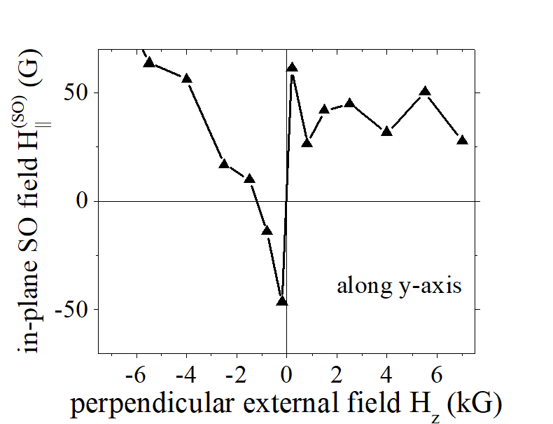
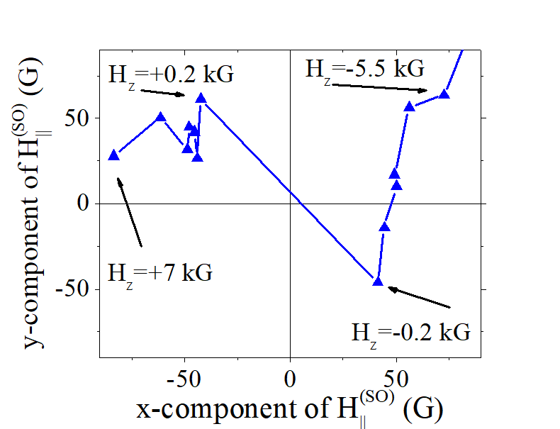
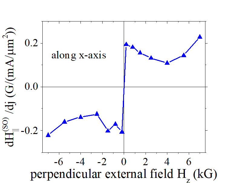
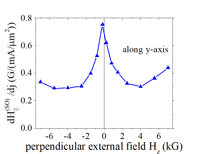
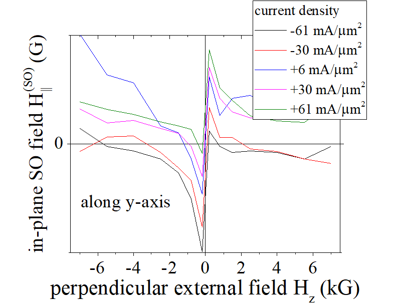
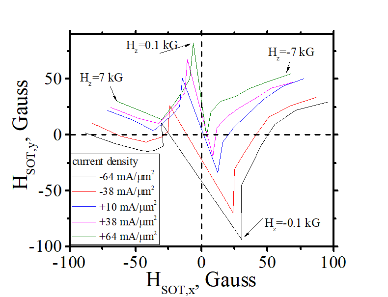
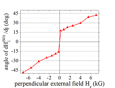
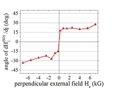
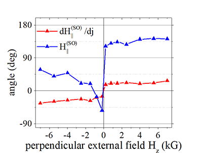
(fact ) ![]() Both the magnitude and the direction of the in-plane current- dependent SO field also depends on direction of the externally- applied perpendicular magnetic field Hz. Its component along current (x- component) reverses its polarity when Hz is reversed. Its magnitude is nearly a constant with a weak oscillations. The component perpendicular to current (y- component) has a maximum at Hz=0 and decays at larger Hz. The y- component does not change polarity.
Both the magnitude and the direction of the in-plane current- dependent SO field also depends on direction of the externally- applied perpendicular magnetic field Hz. Its component along current (x- component) reverses its polarity when Hz is reversed. Its magnitude is nearly a constant with a weak oscillations. The component perpendicular to current (y- component) has a maximum at Hz=0 and decays at larger Hz. The y- component does not change polarity.
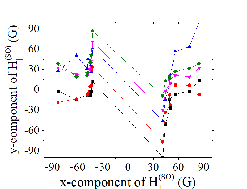
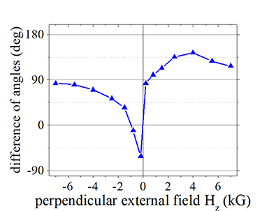
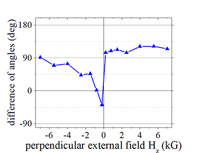
(fact ) ![]() Dependencies of in- plane magnetic field on external magnetic field and on electron current seems to be always perpendicular each other (See Fig.7 and Fig.2f). For example, the direction of a change of H||, when the current increases, is about perpendicular to the direction change due to a change of Hz. It implies both dependencies have the same origin.
Dependencies of in- plane magnetic field on external magnetic field and on electron current seems to be always perpendicular each other (See Fig.7 and Fig.2f). For example, the direction of a change of H||, when the current increases, is about perpendicular to the direction change due to a change of Hz. It implies both dependencies have the same origin.
(fact ) ![]() The dependence of H|| on current density is perfectly linear (See Fig.3) even at a higher current without visible ~I2 dependence . At current density of 100 mA/ μm2 the nanomagnet is heated up to 70-80 C. As following Curie-Weiss law (See here), the magnetization (the total spin of localized electrons) reduced for about 3-4 %. The measured parameters for the same nanomagnet, which is linearly depends on the total spin of the localized electrons (e.g. the coercive field, the anisotropy field, Anomalous Hall effect), follow ~I2 and are reduced about 3-4 %. It implies that the current-induced in-plane magnetic field H|| is not proportional and is not influenced by the total magnetic moment of localized electrons. It can be either proportional to Oersted Field induced by the current or the total spin of the conduction electron due to the Spin Hall effect.
The dependence of H|| on current density is perfectly linear (See Fig.3) even at a higher current without visible ~I2 dependence . At current density of 100 mA/ μm2 the nanomagnet is heated up to 70-80 C. As following Curie-Weiss law (See here), the magnetization (the total spin of localized electrons) reduced for about 3-4 %. The measured parameters for the same nanomagnet, which is linearly depends on the total spin of the localized electrons (e.g. the coercive field, the anisotropy field, Anomalous Hall effect), follow ~I2 and are reduced about 3-4 %. It implies that the current-induced in-plane magnetic field H|| is not proportional and is not influenced by the total magnetic moment of localized electrons. It can be either proportional to Oersted Field induced by the current or the total spin of the conduction electron due to the Spin Hall effect.
|
||||
| Sample Volt 54a\R42C SOT. Click here to check all data | ||||
| Click on image to enlarge it |
Measurement of SO in-plane magnetic field H||. Dependence on current density |
|||||||||||||||||||||
|
|||||||||||||||||||||
The current dependence of In-plane spin-orbit magnetic field H|| |
|||||||||||||||||||||
| sample Volt 54a nanomagnet R42C. Size 3000 nm x 3000 nm. See more details about sample here. | |||||||||||||||||||||
| Click on image to enlarge it |
Fig.3 Dependence of SO in-plane magnetic field H||on current density |
||||||||
|
||||||||
|
||||||||
| Click on image to enlarge it |
High- precision measurement of SO in-plane magnetic field |
|||
|
|||
|---|---|---|---|
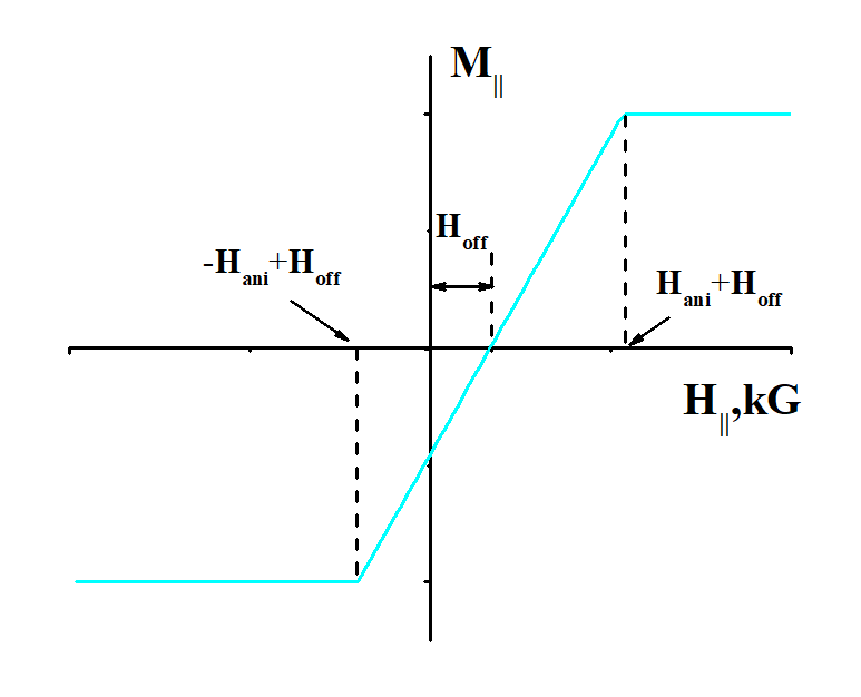
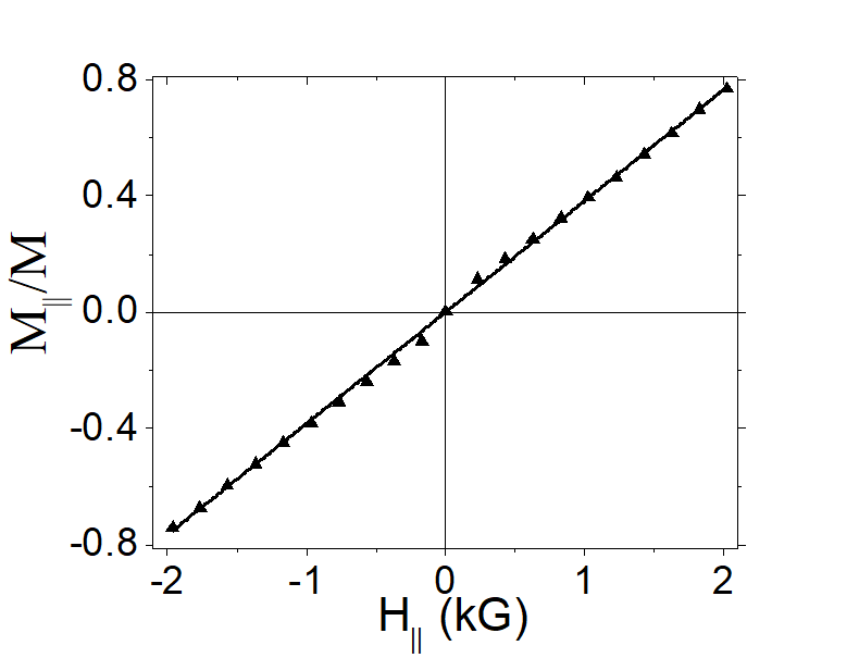
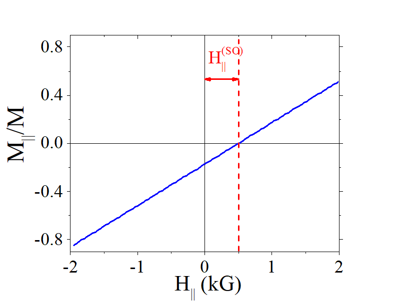
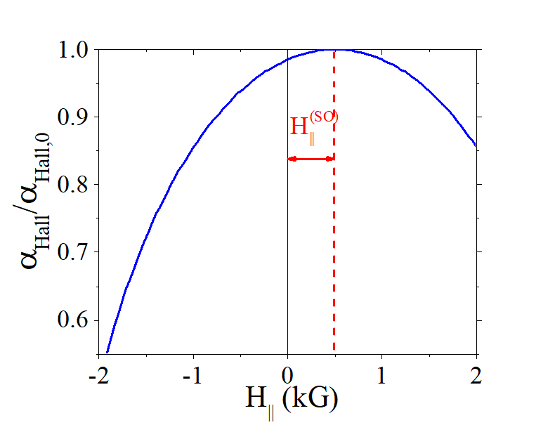
| External magnetic field H|| is applied in-plane and perpendicularly to the magnetization (along a hard axis). As a result, the magnetization turns towards the magnetic field. The dependence of M|| vs. H|| is linear. However, the line does not pass through the axis center and there is an offset magnetic field Hoff . This offset magnetic field Hoff is the intrinsic in-plane magnetic field, which is aimed for the measurement in this method. | |||
| (what is measured) |
|||
|
|||
Note. I have developed this measurement method in 2019-2020 |
|||
| Click on image to enlarge it |
A magnetic parameter, which depends symmetrically on an applied in- plane magnetic field Hext, is measured. Due to existence of the intrinsic magnetic field the measured data is shifted with respect to the axis center Hext,. Adding the offset field Hoff as a parameter, the data symmetrized with respect to a reversal of (Hext,+Hoff). The minimum square difference between data (Hext,+Hoff) and data(-(Hext,+Hoff)) gives the required intrinsic magnetic field H||
(in short: how measurement is done)  :
:
The Hall angle αHall is measured under a scan in-plane magnetic field H||. The measurement is not symmetric with respect to a reversal of H|| due to the intrinsic magnetic field. The intrinsic magnetic field is evaluated from the shift of the measured dependence of αHall vs. H||.
Measurement behind the measurement method. Measurement of anisotropy field |
||||||
|
||||||
Measurement of the anisotropy field of a magnetic nanowire. The green balls shows the magnetization direction of FeB nanomagnet, the blue arrow shows direction of external magnetic field. The FeB nanomagnet is fabricated on top of Ta nanowire. The magnetization direction is measured by a pair of Hall probe. The measured Hall voltage is largest when the magnetization is perpendicular to the top surface of nanomagnet |
||||||
| Without an external magnetic, the magnetization M is perpendicular to the film due to PMA. When external in-plane magnetic field H|| is applied, the magnetization turns towards the H||. The magnetic field, at which the magnetization turns fully in-plane is called the anisotropy field. The stronger PMA is and the stronger the PMA resists to the magnetization turning, the lager and the anisotropy filed is. Therefore, the anisotropy field is measure of the strength of the PMA. | ||||||
|
||||||
Measurement in presence on intrinsic in-plane magnetic field |
||||||
|---|---|---|---|---|---|---|
|
||||||
| Click on image to enlarge it |
(The measurement behind the proposed measurement method): Measurement of Anisotropy filed Ha (See here and here)
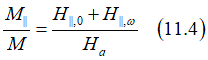
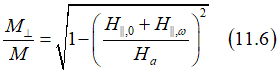
In an equilibrium the magnetization direction is along the easy axis. When an external magnetic field is applied perpendicular to the easy axis, the magnetization is inclined toward the field. The magnetic field, at which the magnetization is fully turns along the field and perpendicularly to the easy axis (along the hard axis), is called the anisotropy field Ha. In the case of a nanomagnet with perpendicular magnetic anisotropy (PMA), the external magnetic field is applied in the in-plane direction. The feature of the PMA is that the in-plane component of the magnetization M|| linearly depends on an external in-plane magnetic field H||:
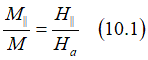
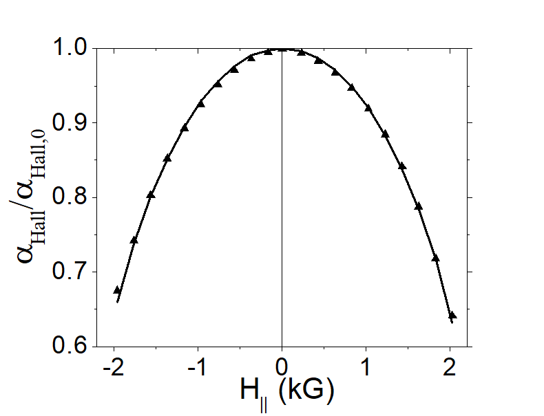
The measured Hall angle αHall is proportional to the perpendicular component of the magnetization:
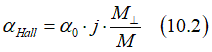
and therefore the dependence is non-linear with respect to H||:
![]() For the proposed high- precision measurement, the specific dependence of αHall vs H|| is not important. It is only important that the dependence is symmetrical with respect to a polarity reversal of H||. As a result, a shift of the symmetry point due to the intrinsic magnetic field can be easy evaluated.
For the proposed high- precision measurement, the specific dependence of αHall vs H|| is not important. It is only important that the dependence is symmetrical with respect to a polarity reversal of H||. As a result, a shift of the symmetry point due to the intrinsic magnetic field can be easy evaluated.
Fitting Method |
 |
Fig.11. Method: Fitting to each other the positive and negative parts of the the measured dependence of αHall on external magnetic field H|| |
| Click on image to enlarge it |
In order to evaluated a symmetry shift of the measured dependence of αHall vs H||. , the dependence of αHall vs |H||+Hoff| is analyzed, where Hoff is a fitting parameter. There are two curves corresponding to the positive and negative part of the dependence. The scanning of Hoff and minimizing the square difference between curves give the value of the intrinsic magnetic field.
in short: 2nd harmonic method
Measurement method of 2nd harmonic. |
 |
In this method, the 2nd harmonic of the Hall voltage is measured while applying a modulated electron current. The electron current j (indicated by the red arrow) modulates the direction of magnetization. As the Hall voltage is directly proportional to both the electrical current and the perpendicular component of magnetization, the resulting frequency beating between these two modulated components gives rise to the 2nd harmonic of the Hall voltage. Consequently, the signal of the 2nd harmonic is proportional to the modulation of magnetization by an electrical current. |
| Click on image to enlarge it |
A low- frequency (50-500 Hz) AC voltage is applied and the second harmonic of the Hall voltage is measured by a lock-in amplifier.

The AC current creates intrinsic in-plane magnetic field, which makes the the magnetization wabble with the same frequency. The Hall voltage is modulated by both the AC current and modulated magnetization. The frequency beating gives the 2nd harmonic.
 Detailed calculation
When an AC voltage Vω
![]()
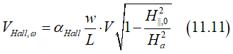
is applied to a nanowire, there is an AC current jω which induces in spin-orbit magnetic field H||,ω (See fig. 2 above) as
![]()
where ζ and κ are constants. κ= ζ/R, where R is the nanowire resistance.
The total in-plane magnetic field is
![]()
where H||,0 is the sum of the externally applied magnetic filed and spin-orbit intrinsic in-filed, which is proportional to an external perpendicular magnetic field (See Fig.1).
Any type of in-plane magnetic field forces the magnetization to turn slightly into its direction. The the in-plane component of the magnetization M|| is linearly proportional to an in-plane magnetic field H||(See here and here):
When a current flows perpendicularly to a the magnetization, there is a Hall voltage due the Anomalous Hall effect, which is proportional to the electrical current, perpendicular component of the magnetization M⊥ is and the Hall angle αHall :
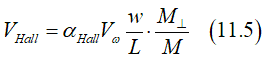
where w and L is nanowire width and length. The perpendicular component of the magnetization M⊥can be calculated from Eq.(11.4) as
Assuming
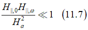
Eq.(11.6) can be simplified as

Substitution of Eq.(11.8) into (11.5) gives the Hall voltage as
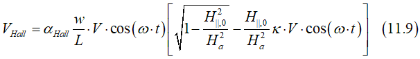
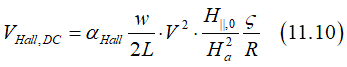
It has a DC-component VHall,DC
and 1st harmonic -component VHall,ω
2nd harmonic -component VHall,ω
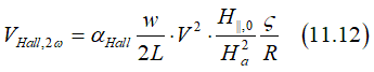
where αHall is the Hall angle of a ferromagnetic metal, w,L,R are width,length and resistance of nanowire, V is amplitude of AC voltage, Ha is the anisotropy filed, which should be measured by this experiment, H||,0 is total in-plane magnetic field, which includes the external filed and SO field (See fig.1), ζ is proportionately coefficient of current- generated SO field and current density.
(note)![]() The 2nd harmonic, as a non-linear effect, is proportional to square of applied voltage V. As a result, in order to be detected it requires a substantial applied voltage (~1-5 V). The amplitude of the corresponding current is large and is about ~30-100 mA/ μm2
The 2nd harmonic, as a non-linear effect, is proportional to square of applied voltage V. As a result, in order to be detected it requires a substantial applied voltage (~1-5 V). The amplitude of the corresponding current is large and is about ~30-100 mA/ μm2
(golden mine)  Since the 2nd harmonic measurement gives a complex result (See Eq.11.12), which depends on many parameters, and has several sharp changes and polarities changes (See Fig.1 and Fig.2) , this measurement has been a golden mine for the "faked" and "highlight" research. Maybe hundreds of papers have been published on this topic with many different fantasy stories, which have nothing to do with the reality.
![]() . It is a good example of a topic, around which the faked research is concentrated. In a case when an experimental result has no immediate clear explanation, it is a good chance to ignore all Laws of Physics and to start making the "Harry- Potter style" research stories.
. It is a good example of a topic, around which the faked research is concentrated. In a case when an experimental result has no immediate clear explanation, it is a good chance to ignore all Laws of Physics and to start making the "Harry- Potter style" research stories.
Measurement of SO in-plane magnetic field H||. Dependence on an external magnetic field Hz |
|||||||||||||||||||||
|
|||||||||||||||||||||
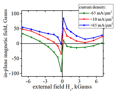
In-plane spin-orbit magnetic field H|| vs. external perpendicular magnetic field Hz. |
|||||||||||||||||||||
| sample Volt 54B nanomagnet ud 66. Size 200 nm x 500 nm See more details about sample here. | |||||||||||||||||||||
| Click on image to enlarge it |
Measurement of SO in-plane magnetic field H||. Dependence on current density |
|||||||||||||||||||||
|
|||||||||||||||||||||
In-plane spin-orbit magnetic field H|| vs. external perpendicular magnetic field Hz. |
|||||||||||||||||||||
| sample Volt 54B nanomagnet ud 66. Size 200 nm x 500 nm See more details about sample here. | |||||||||||||||||||||
| Click on image to enlarge it |
Fig.7 |
angle of dH||/dj |
Comparison of angles of dH||/dj and H|| |
Difference of angles of dH||/dj and H|| |
|---|---|---|---|
 |
 |
 |
 |
 |
 |
 |
 |
Amplitude of |
||||
|
||||
|
||||
| Click on image to enlarge it |
![]() What is the magnetic torque? At which condition it occurs?
What is the magnetic torque? At which condition it occurs?
Wiki definition of the torque see here
(field-like torque. Torque or not?) : When electron spin is not aligned to an external magnetic field, there is a spin precession around the magnetic field. In classical physics assumes that the precession is caused by a torque, which is called the field- like torque. However, the quantum mechanic understands the spin precession as one stable states of the spin. The spin precession is the spin state when the electron energy is between spin-up and spin- down states, when the magnetic energy is the largest and smallest. Due to the spin conservation law, the angle of the spin precession can be changed only when interact with another particle, which has non-zero spin.
![]() The electron spin interacts with the total magnetic field, which is a vector sum of all possible magnetic fields applied. The common magnetic fields are (1) external magnetic field (2) magnetic field of the spin- orbit interaction; (3) effective field of the exchange interaction.
The electron spin interacts with the total magnetic field, which is a vector sum of all possible magnetic fields applied. The common magnetic fields are (1) external magnetic field (2) magnetic field of the spin- orbit interaction; (3) effective field of the exchange interaction.
(note about intrinsic magnetic fields) ![]() An electron in a solid always experiences several magnetic fields (e.g. magnetic field of the spin- orbit interaction; effective field of the exchange interaction). The electron spin is aligned along a vector sum of all these magnetic fields. In a case a huge external magnetic field is applied, of course, the spin is along this field. In the reality, an external magnetic field or an intrinsically- generated field (e.g. by the Spin Hall effect) are smaller or comparable to the magnetic field, which the electron already experiences.
An electron in a solid always experiences several magnetic fields (e.g. magnetic field of the spin- orbit interaction; effective field of the exchange interaction). The electron spin is aligned along a vector sum of all these magnetic fields. In a case a huge external magnetic field is applied, of course, the spin is along this field. In the reality, an external magnetic field or an intrinsically- generated field (e.g. by the Spin Hall effect) are smaller or comparable to the magnetic field, which the electron already experiences.
(note about thermally- activated switching) ![]() Details see here. At a non-zero temperature, the electron interacts with many non-zero-spin particles (e.g. a photon, a spin wave), the spin is transformed from those particles to electron, which causes a spin precession around the existed magnetic field. Since the spin precession of different electron is in different phases, overall all spin precessions looks like the spin swinging (See here). For example, the average spin-swinging angle in Fe is 12 deg. at room temperature(See here). The spin swinging is a statistical process and there is a probability of swinging angle larger than 90 degrees, after which the magnetization is reversed. This process is called the thermally- activated switching and it is strongly influenced by an external magnetic field (see here). However, this process has nothing to with a torque.
Details see here. At a non-zero temperature, the electron interacts with many non-zero-spin particles (e.g. a photon, a spin wave), the spin is transformed from those particles to electron, which causes a spin precession around the existed magnetic field. Since the spin precession of different electron is in different phases, overall all spin precessions looks like the spin swinging (See here). For example, the average spin-swinging angle in Fe is 12 deg. at room temperature(See here). The spin swinging is a statistical process and there is a probability of swinging angle larger than 90 degrees, after which the magnetization is reversed. This process is called the thermally- activated switching and it is strongly influenced by an external magnetic field (see here). However, this process has nothing to with a torque.
(note 1) The magnetic field Hexchange is huge, but it describes only the interaction between
(note 2) The exchange interaction is poorly described by the magnetic field Hexchange.
(note 3) The exchange interaction only fixes the alignment between spins. When such alignment is considered as one object (a magnetic domain) with a single spin, the Hexchange can be ignored.
(note 1) The magnetic field HSO is huge, but it describes only the interaction between
(note 2) The magnetic field HSO depends on degree of breaking of symmetry of the orbital moment. As a result, the HSO dependents on the direction of the electron spin with respect to orbital symmetry.
| Comparission between differrnt sample | ||||||||||||
|---|---|---|---|---|---|---|---|---|---|---|---|---|
|
||||||||||||
Measurement method of current-induced in- plane magnetic field |
|||
|
|||
| Dependence of in-plane component of magnetization on in-plane plane magnetic field. The magnetic field is applied in-plane and along the current. HFL is the the offset magnetic field, which is proportional to the current. The HFL is evaluated by linear fitting of the dependence, which measured in Hall configuration. | |||
| Click on image to enlarge it |
This method is similar to the method of measurement of anisotropy field Hanis (See here). In this measurement the in-plane component of the magnetization is measured as a function of an external magnetic field Hext. The dependence is linear (See here). Therefore, it can be measured with a high precision. The anisotropy field Hanis is defined as the in-plane magnetic field, at which initially-perpendicular magnetization turns completely into the in-plane direction.
Under a sufficient bias current, additionally to Hext., there are two more additional magnetic fields: 1) effective field of "field-like" torque HFL in direction of current and 2) effective field of "damp-like" torque HDL in direction perpendicularly to the current. Therefore, the magnetization experiences two magnetic field:
In-plane magnetic field along bias current (the x-axis) Htotal,x=Hext,x+HFL ,
In-plane magnetic field perpendicularly to bias current (the y-axis) Htotal,y=Hext,y+HDL ,
As a result, the dependence M vs Hext is shifted on HFL (Hext is applied along x-axis) or HDL (Hext is applied along y-axis). From the shift the HFL are HDL are evaluated.
![]() Note: The same measurements can be done by two method
Note: The same measurements can be done by two method
Method 1. The direct measurement using a nano voltmeter (See Fig.2 above)
Method 2. The 2nd-harmonic measurement using a lock-in amplifier (See here)
Both measurements give the same values of HFL and HDL and nearly the measurement precision. However, the usage of the direct measurement is preferable for the following reasons. ![]() From the direct measurement, the dependence of HFL and HDL on bias current can be evaluated.
From the direct measurement, the dependence of HFL and HDL on bias current can be evaluated.![]() From measured dependence of M vs H, the contributions of the "field-like" and "damp-like" torque can be separated in the case when they are in the same direction. In contrast to the 2nd-harmonic measurement, in the direct measurement the undesired contribution due to sample heating can be removed.
From measured dependence of M vs H, the contributions of the "field-like" and "damp-like" torque can be separated in the case when they are in the same direction. In contrast to the 2nd-harmonic measurement, in the direct measurement the undesired contribution due to sample heating can be removed.
Additional data |
||||
|
||||
|
||||
| Click on image to enlarge it |
 Video
Video 
Parametric magnetization reversal. Spin- orbit torque Conference presentation. Intermag 2021 |
|---|
|
![]()
![]() I am strongly against a fake and "highlight" research
I am strongly against a fake and "highlight" research ![]()
![]()
![]()
![]()
![]()
![]()
I will try to answer your questions as soon as possible

 The origin of this in-plane magnetic field is the spin-orbit interaction.