Dr. Vadym Zayets
v.zayets(at)gmail.com
My Research and Inventions
click here to see all content |

Dr. Vadym Zayetsv.zayets(at)gmail.com |
|
|
more Chapters on this topic:IntroductionTransport Eqs.Spin Proximity/ Spin InjectionSpin DetectionBoltzmann Eqs.Band currentScattering currentMean-free pathCurrent near InterfaceOrdinary Hall effectAnomalous Hall effect, AMR effectSpin-Orbit interactionSpin Hall effectNon-local Spin DetectionLandau -Lifshitz equationExchange interactionsp-d exchange interactionCoercive fieldPerpendicular magnetic anisotropy (PMA)Voltage- controlled magnetism (VCMA effect)All-metal transistorSpin-orbit torque (SO torque)What is a hole?spin polarizationCharge accumulationMgO-based MTJMagneto-opticsSpin vs Orbital momentWhat is the Spin?model comparisonQuestions & AnswersEB nanotechnologyReticle 11
|
Magneto transport. Family of Hall effects and AMR effects. Spin and Charge TransportAbstract:The family of the Hall effects or the magneto- transport effects are described. These effects are classified based on their symmetry with respect to the reversal of a magnetic field and the flow direction of the magnetically induced current (the Hall current) . When the induced current flows parallel to the main bias current, it modifies the wire’s resistivity, giving rise to a variety of Magnetoresistance effects (e.g. the Anisotropic Magnetoresistance (AMR) effect). When the magnetically induced current flows perpendicular to the wire, charge accumulates along the sides, creating a voltage across the wire known as the Hall voltage, and the phenomenon is referred to as the Hall effect.
|
|
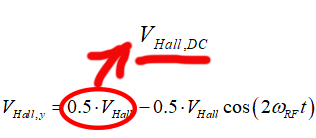
Local nature of spin- orbit interaction as origin of spin- dependent scatterings |
||||||
|
||||||
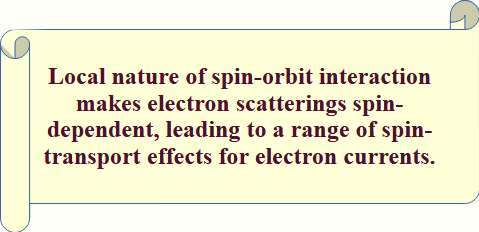
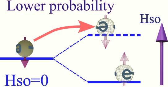
The electron is scattering from a quantum state, which does not experience any spin- orbit interaction to a state where the magnetic field of spin- orbit interaction is directed up. |
||||||
The spin-dependency of electron scattering is the origin for a variety of magneto-transport effects. |
||||||
 |
||||||
(fact) Local nature of spin- orbit interaction is he basis for a variety of magneto-transport effects. |
||||||
| Spin-dependency of electron scatterings is substantial for scatterings across the interface and scatterings in the vicinity of an interface. For instance, when an electron scatters across an interface, it encounters a markedly different spin-orbit interaction field on either side of the interface. | ||||||
| click on image to enlarge it |
![]() .........
......... ![]()
There are ![]() four first-order Hall effects, each described by the expression:
four first-order Hall effects, each described by the expression:
![]()
where jHall is the Hall current, j is the ordinary current, and V is a vector that reverses sign under time inversion and α is proprtionality constant. These effects are:
![]() (effect 1) Ordinary Hall Effect, proportional to the external magnetic field Hext.
(effect 1) Ordinary Hall Effect, proportional to the external magnetic field Hext.
![]()
![]() (effect 2)Anomalous Hall Effect, proportional to the magnetization M.
(effect 2)Anomalous Hall Effect, proportional to the magnetization M.
![]()
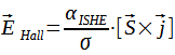
![]() (effect 3) Inverse Spin Hall Effect, proportional to the total spin of spin-polarized conduction electrons S.
(effect 3) Inverse Spin Hall Effect, proportional to the total spin of spin-polarized conduction electrons S.
![]()
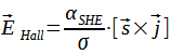
(![]() effect 4) Spin Hall Effect, describing generation of the spin current from the charge current. The spin current jspin. jis proportional to the angle between the charge current j and direction of spin accamulated electrons s
effect 4) Spin Hall Effect, describing generation of the spin current from the charge current. The spin current jspin. jis proportional to the angle between the charge current j and direction of spin accamulated electrons s
![]()
For the first-order Hall effects, the Hall current flows perpendicular to the charge current.
It is often convenient to use the Hall angle,which shows the direction where the total current flows, as:
![]()
The second-order Hall effects, described by either:
![]()
or
![]()
In the second case, the Hall current flows only in the direction of the charge current. In the first case, however, the Hall current has two components: one parallel to the charge current and another perpendicular to it.
When the Hall current flows parallel to the charge current, the total current—under the same applied voltage—can increase or decrease due to the contribution of the Hall current. This means that the magnetic effect alters the resistance of the conductor. Consequently, this magnetic effect is referred to as magnetoresistance.
Many second-order Hall effects are known, including the AMR/PHE effect (Anomolous Magnetoresistance / Planar Hall Effect) as well as Giant Magnetoresistance (GMR).
The AMR/PHE effect is a single second-order Hall effects, for which AMR describes along- bias current component of magneto- current and PHE describes the perpendicular component.
 (Minor origin) Relativistically generated electric field (Lorentz force)
When an electron moves through a magnetic field, it experiences a force known as the Lorentz force, which can be interpreted as the result of an electric field appearing in the electron’s rest frame. The origin of this field is relativistic: due to the relativistic nature of electromagnetic fields, magnetic and electric components transform into each other when observed from different inertial frames. In a stationary reference frame where only a magnetic field is present, an observer moving with the electron will detect both an electric and a magnetic field. The interaction between this induced electric field and the electron’s charge results in the Lorentz force, influencing the electron’s trajectory.
![]() (Major origin) Spin-dependent scattering
(Major origin) Spin-dependent scattering
During electron transport, electrons undergo frequent scattering events caused by various mechanisms. The characteristics of these scattering events largely determine the transport properties. When the scattering probabilities differ depending on the spin orientation of the electron or the surrounding electrons, the transport becomes spin-dependent. Spin-dependent scattering is the primary origin of most magnetotransport effects.
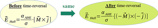
Any magnetotransport effect must obey time-reversal symmetry (T-symmetry). This means that the equations describing the magnetotransport effect should remain unchanged when the direction of time is reversed. Second-order magnetotransport effects naturally satisfy T-symmetry. However, first-order magnetotransport effects do not. This observation suggests that the general expression for first-order magnetotransport effects must be modified. After applying these modifications, the equations describing first-order magnetotransport effects become symmetric under time reversal (i.e., they become T-symmetric).
![]()
 Effect of time reversal:
polarity reversed:
magnetic field +H →-H; spin +S→-S; ; magnetization +M →-M; ; charge current +j →-j; ; Hall current +jHall→ -jHall;
no change of polarity :
electrical field E →E;
----------
![]() Time- reversal for 2nd order magneto-transport effect (AMR/PHE effect as an example):
Time- reversal for 2nd order magneto-transport effect (AMR/PHE effect as an example):
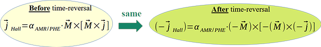
 (result): 2nd- order magneto-transport effects are T-symmetrical
-----------------
![]() Time- reversal for 1st- order magneto-transport effect (AHE effect as an example):
Time- reversal for 1st- order magneto-transport effect (AHE effect as an example):
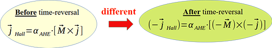
![]() (result): Are 1st- order magneto-transport effects not T-symmetrical
(result): Are 1st- order magneto-transport effects not T-symmetrical![]() . It cannot be the case. The 1st- order magneto-transport effects have to be T- symmetrical.
. It cannot be the case. The 1st- order magneto-transport effects have to be T- symmetrical.
In order to make the 1st order Hall effects to be T- symmetrical, in the formula for the effect the Hall current should be replaced by the Hall electrical field or the Hall voltage.
![]() (fact): The first-order and second-order Hall effects must be symmetric under time reversal, as their underlying mechanisms—the Lorentz force and spin-dependent scattering—are themselves symmetric with respect to time reversal.
(fact): The first-order and second-order Hall effects must be symmetric under time reversal, as their underlying mechanisms—the Lorentz force and spin-dependent scattering—are themselves symmetric with respect to time reversal.
 (reason): Ohm law:
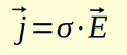 is not T-symmetrical!!
where σ is conductivity
The reversal of time reverses the current, but does not affect the electrical field.
It is the known fact that the Ohm law is not T- symmetrical for reasons explained here.
(important) If Ohm’s law is used in the expression for the first-order Hall effect, it artificially breaks the inherent time-reversal symmetry of the Hall effect.
![]() (fact): The usage of the Hall electrical field or the Hall voltage instead of the Hall current restores inherent T-symmetry for description formula of the 1st order Hall effects
(fact): The usage of the Hall electrical field or the Hall voltage instead of the Hall current restores inherent T-symmetry for description formula of the 1st order Hall effects
In the modified formula for the 1st order Hall effects, the Hall electrical field is used instead of the Hall current
![]() Time- reversal for modified 1st- order magneto-transport effect (modified AHE effect as an example):
Time- reversal for modified 1st- order magneto-transport effect (modified AHE effect as an example):
Modified formula for 1st- order Hall effects are:
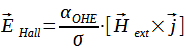
![]() (effect 1) Ordinary Hall Effect, proportional to the external magnetic field Hext.
(effect 1) Ordinary Hall Effect, proportional to the external magnetic field Hext.
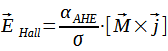
![]() (effect 2)Anomalous Hall Effect, proportional to the magnetization M.
(effect 2)Anomalous Hall Effect, proportional to the magnetization M.
![]() (effect 3) Inverse Spin Hall Effect, proportional to the total spin of spin-polarized conduction electrons S.
(effect 3) Inverse Spin Hall Effect, proportional to the total spin of spin-polarized conduction electrons S.
(![]() effect 4) Spin Hall Effect, describing generation of the spin current from the charge current. The spin current jspin. is proportional to the angle between the charge current j and direction of spin accamulated electrons s
effect 4) Spin Hall Effect, describing generation of the spin current from the charge current. The spin current jspin. is proportional to the angle between the charge current j and direction of spin accamulated electrons s
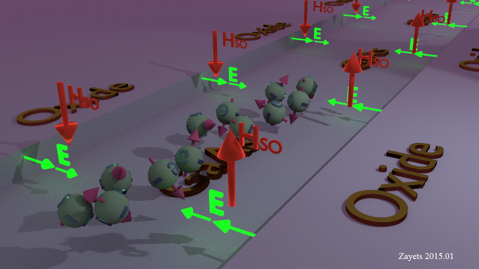
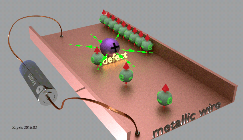
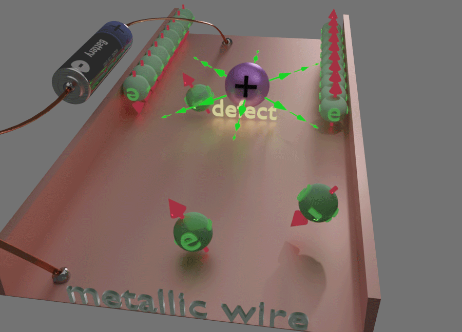
Spin- Orbit interaction as the origin of Inverse Spin Hall effect (ISHE) |
|||||||||
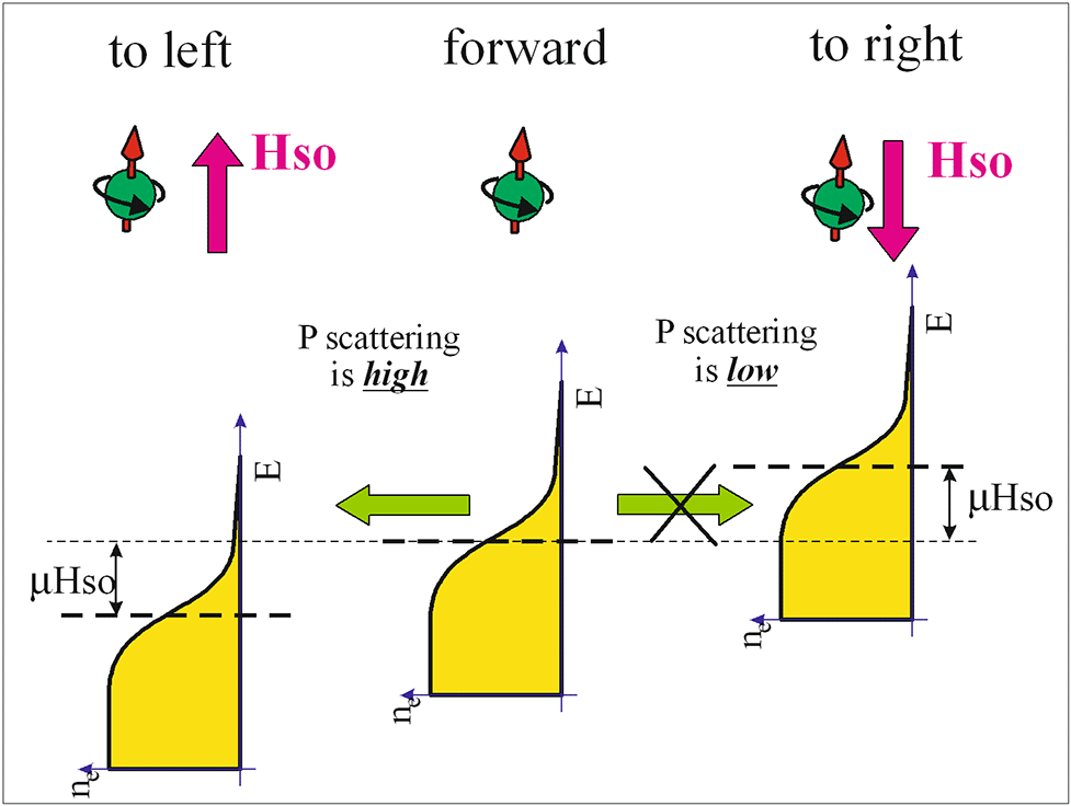
| The origin of ISHE is the spin- dependent scatterings. There are several mechanisms, which make scatterings of conductions electrons spin- and direction- dependent. (mechanism 1): due to a non-zero orbital moment of conduction electrons; (mechanism 2): Skew scatterings (mechanism 3): Side-jump scatterings at defect (mechanism 4): Side-jump scatterings across an interface. Independently on the mechanism, the origin of ISHE is the same. The conduction electron experiences the magnetic field HSO of the spin-orbit interaction, which depends either on the electron movement direction (kx, ky, kz) or the electron spacial position (x, y, z) . The HSO makes scatterings of conductions electrons spin- and direction- dependent. As a result of the spin- and direction- dependency of scattering probability, the numbers of spin-polarized electrons, which are scattered to the left and to the right, are different and there is an electron current (charge current) flowing perpendicularly to the main current | |||||||||
|
|||||||||
| note: |
|||||||||
| click on image to enlarge it |
 a magnetically- generated current is linearly proportional to current jbias
 a magnetically- generated current is reversed its polarity when to current jbias is reversed
a magnetically- generated current is proportional either an external magnetic field H or/and total spin of localized electrons Slocal or/and total spin of conduction electrons Scond .an electrical current should change distribution of at least one magnetic property of conduction electrons. It should change the distribution of spins or orbital momentsAll magneto- transport effects can be distinguished by their symmetry against reversal of substantially large magnetic field, which fully reverses spins of localized and conduction electrons.
 (), which polarity is not reversed when the magnetic field and the spins are reversed
Polarity of effect is Reversed, when when the magnetic field + spin are reversed
Ordinary Hall effect (OHE), Anomalous Hall effect, Inverse Spin Hall effect
 , which polarity is not reversed when the magnetic field and the spins are reversed
Polarity of effect is NOT Reversed, when when the magnetic field + spin are reversed
Anisotropic Magneto- resistance (AMR), Planar Hall effect, , spin detection effect
 Ordinary Hall effect (OHE)
Ordinary Hall effect (OHE) |
||||||||||||
|
||||||||||||
| click on image to enlarge it |
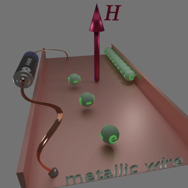
(origin) Origin of OHE is the Lorentz force. An electron experience an relativistic electrical field due to electron movement perpendicularly to the magnetic field. The The relativistic electrical field interacts with the electron charge (not spin) forcing the electron to move in its direction.
(interact with) ![]() Electron Charge of conduction electrons
Electron Charge of conduction electrons
![]() OHE is linearly proportional to an external magnetic field H
OHE is linearly proportional to an external magnetic field H
(formula):
![]()
aOH is the rotation angle of the ordinary Hall effect (in mdeg/kG). H is external magnetic field. aOH is positive for the hole- dominated conductivity. aOH is negative for the electron- dominated conductivity. jV is the bias current along metallic wire (from electrical source to electrical drain). The hole- dominated conductivity in a material, in which density of states decreases at the Fermi level. The electron- dominated conductivity in a material, in which density of states decreases at the Fermi level. jHall is electrical current flowing perpendicular to wire; jV is electrical current flowing along to wire due to applied voltage V;
(note) ![]() The OHE is independent of the spins of localized and conduction electrons. It depends on the charge of carrier and its transport properties.
The OHE is independent of the spins of localized and conduction electrons. It depends on the charge of carrier and its transport properties.
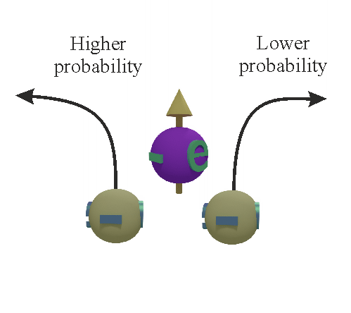
Anomalous Hall effect (AHE)Anomalous Hall effect (AHE) |
|---|
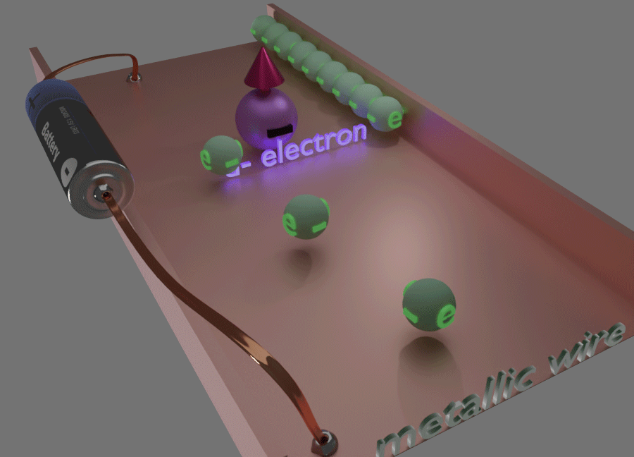 |
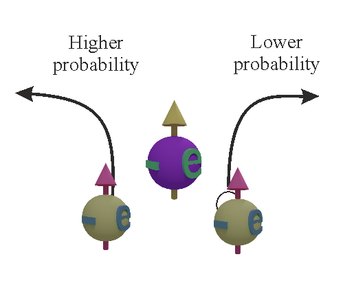
| (definition) The AHE describes the fact that charge is accumulated at sides of metallic wire, when the spins of localized d- electrons are in one direction (e.g. ferrimagnetic state) perpendicularly to the wire and an electron current flows through the wire |
| The conduction electrons (green balls) interacts with the aligned spin of localized d- electrons(blue ball). Due to such interaction the scattering probability of conduction electrons to the right becomes larger than to the left and they are accumulated at the right side of the wire. |
| click on image to enlarge it |
(origin) Dependence of scattering of conduction electrons on the spin of localized electrons
(interact with)  Rotational (Orbital) Moment of conduction electrons
![]() AHE is linearly proportional to the total spin of localized electrons.
AHE is linearly proportional to the total spin of localized electrons.
(formula):
![]()
aAH is the rotation angle of the Anomalous Hall effect (in mdeg). Slocal is the total spin of localized electrons. Since in the most of realistic cases, only the direction , but not magnitude of Slocal changes, Eq. can be simplified as
![]()
where M is an unit vector in direction of magnetization; jHall is electrical current flowing perpendicular to wire; jV is electrical current flowing along to wire due to applied voltage V;
(note) ![]() The AHE depends on the total spin of localized d- electrons, but they are independent of the total spin of conduction electrons.
The AHE depends on the total spin of localized d- electrons, but they are independent of the total spin of conduction electrons.
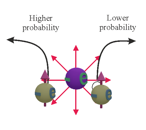
Inverse Spin Hall effect (ISHE)Inverse Spin Hall effect (ISHE) |
|---|
 |
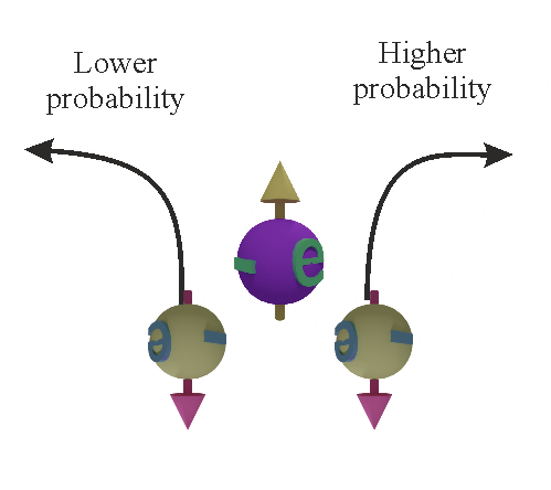
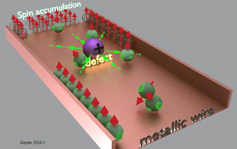
| (definition) The ISHE describes the fact that charge is accumulated at sides of metallic wire, when the conduction electrons are spin- polarized and an electron current flows through the wire |
| The conduction electrons (green balls) are scattered on a charged defect (blue ball). The conduction electrons are spin- polarized (spin- up). Due to the spin-orbit interaction, the scattering probability for spin-up electrons is higher for a scattering to the right than to the left. As a result, the electrons (the charge) is accumulated at the right side of wire |
| click on image to enlarge it |
(origin) Dependence of scattering of conduction electrons on the spin of localized electrons
(interact with) ![]() Rotational (Orbital) Moment of conduction electrons
Rotational (Orbital) Moment of conduction electrons
![]()
![]()
![]() ISHE is proportional to the total spin of conduction electrons
ISHE is proportional to the total spin of conduction electrons
(formula):
![]()
or the same
![]()
where Ps is spin polarization. m is unity vector along spin- direction of spin-polarized conduction electrons; aIIHE is the rotation angle of the Inverse Spin Hall effect (in mdeg); Sconduct is the total spin of conduction electrons; jHall is electrical current flowing perpendicular to wire; jV is electrical current flowing along to wire due to applied voltage V;
 Spin- dependent scatterings
(explanation in short) The spin dependent scatterings means that the scattering probability of spin- up electron is higher to the left![]()
![]() and the scattering probability of spin- down electron is higher to the right
and the scattering probability of spin- down electron is higher to the right ![]()
![]() . For example, if the spin direction of the spin polarized conduction electrons is up, there are more electrons scattered to the left and as a result there is a charge current flowing to the left
. For example, if the spin direction of the spin polarized conduction electrons is up, there are more electrons scattered to the left and as a result there is a charge current flowing to the left
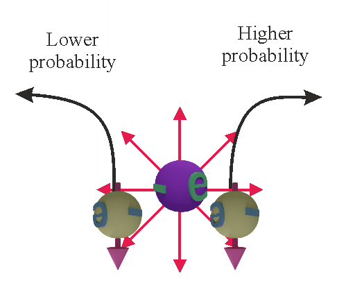
Spin Hall effect (ISHE)Spin Hall effect (SHE) |
|---|
 |
| (definition) The SHE describes the fact that spin is accumulated at sides of metallic wire, when an electron current flows through the wire |
| The conduction electrons (green balls) are scattered on a charged defect (blue ball). The conduction electrons are spin- unpolarized (spins are distributed equally in all directions)). Due to the spin-orbit interaction, the scattering probability for spin-up electrons is higher for a scattering to the right than to the left and in contrast the scattering probability for spin-down electrons is lower for a scattering to the right than to the left. As a result, the spin-up electrons is accumulated at the right side of wire and the spin-down electrons is accumulated at the left side of the wire |
| (note) The SHE redistributes the spin- unpolarized electrons (all spin directions) into two separated places in which the number of either spin-up or spin-down electrons are larger. In total, the the number of electron with spin of a specific direction remains the same. It does not re align electron spin (as for example magnetic field(See here and here) |
| click on image to enlarge it |
(origin) Dependence of scattering of conduction electrons on the spin of localized electrons
(interact with) ![]() Rotational (Orbital) Moment of conduction electrons
Rotational (Orbital) Moment of conduction electrons
![]()
![]()
![]() SHE is proportional to the total spin of conduction electrons
SHE is proportional to the total spin of conduction electrons
(formula):
aAH is the rotation angle of the Anomalous Hall effect (in mdeg). Slocal is the total spin of localized electrons. Since the the total spin of the spin-polarized electrons is linearly proportional to the number of spin polarized electrons, the Eq. can be simplified as
where Ps is spin polarization. m is unity vector along spin- direction of spin-polarized conduction electrons
(note) ![]() Spin Hall effect (SHE) and Inverse Spin Hall effect (ISHE) are fully complementary effect. They have identical origins and in a material they have the same magnitude
Spin Hall effect (SHE) and Inverse Spin Hall effect (ISHE) are fully complementary effect. They have identical origins and in a material they have the same magnitude
(note) ![]() Both the SHE and ISHE depends on the total spin of conduction electrons, but they are independent of the total spin of localized electrons.
Both the SHE and ISHE depends on the total spin of conduction electrons, but they are independent of the total spin of localized electrons.
(note) ![]() The ISHE is linearly proportional to the number of spin- polarized conduction electrons. The SHE is linearly proportional to the number of spin- unpolarized conduction electrons.
The ISHE is linearly proportional to the number of spin- polarized conduction electrons. The SHE is linearly proportional to the number of spin- unpolarized conduction electrons.
Anomalous
 Two parts of the same effect: the Hall effects and Anisotropic Magneto- Resistance (AMR) effect.
The Hall effect and AMR effect are in the same family of effects. The have similar properties, similar origins and similar symmetry.
(a good example) the classic AMR and the Planar Hall effect describes one single effect, which is the magnetic generation of a current parallel to the magnetization direction. The component of this current, which is parallel to the bias current, describes the AMR effect. The component of this current, which is perpendicular to the bias current, describes the Planar Hall effect.
Two twins effects: Hall effect and Anisotropic magneto resistanceThe Hall effect is defined
 Hall effect
 (current
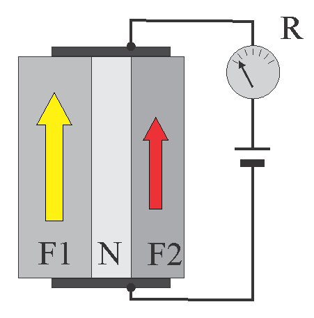
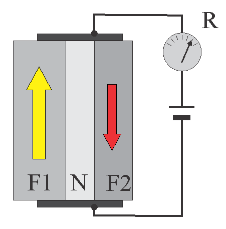
In- plane GMR effect |
||||||
|---|---|---|---|---|---|---|
|
||||||
| F1,F2 are ferromagnetic metals, N is a non-magnetic metal. There is no exchange interaction between ferromagnetic layers. Therefore, their magnetization (shown by arrows) can be changed independently. The resistivity of the wire dependence on mutual directions of the magnetization in each layer. | ||||||
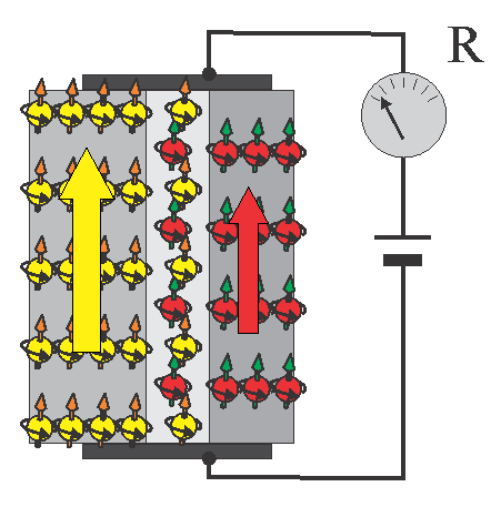
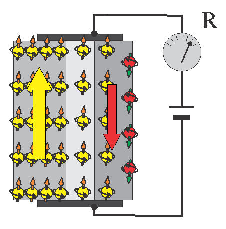
Origin of in-plane GMR effect |
||||||
|
||||||
| Arrows shows the spin direction of localized electrons (magnetization) in ferromagnetic layer. Balls shows the spins of spin- polarized conduction electrons. Color of balls indicates in which layer the conduction electron was made spin- polarized . | ||||||
| Spin-polarization of conduction electrons in the left layer is larger (Fro example, due to a weaker spin relaxation) | ||||||
| (note): Spins of conduction electrons are aligned along spins of localized electrons due to sp-d exchange interaction and sp-d scatterings. (See here). In an equilibrium in a single- material ferromagnetic metal, the spin directions of spin-polarized conduction electrons and localized d- electrons are parallel. | ||||||
| (note) The resistance of a material is smallest when spin directions of spin-polarized conduction electrons and localized d- electrons are the same due to the effect of the spin-dependent conductivity. | ||||||
| click on image to enlarge it |
The in-plane GMR effect describes the fact that resistance of a metallic wire, which consists of two ferromagnetic layers separated by a non-magnetic layer, depends on mutual magnetization directions of two ferromagnetic layers. It is the smallest, when magnetization directions are parallel and it is the largest, when the magnetization directions is opposite.
(origin 1 of in-plane GMR effect) ![]() Spin proximity effect
Spin proximity effect
The spin proximity effect (See details here) describes the fact that the spin polarized conduction electrons diffuses from the first ferromagnetic layer to the second ferromagnetic layer, change the spin polarization in the second layer and as a results the resistivity of the second ferromagnetic layer increases due to the effect of the spin- dependent conductivity.
(origin 2 of in-plane GMR effect) ![]() spin- dependent conductivity.
spin- dependent conductivity.
The conductivity of a ferromagnetic metal depends on mutual directions of spins of localized electrons and spins of conduction electrons. When spin-polarized conduction electrons diffuses from one ferromagnetic metal to the second ferromagnetic layer of a different magnetization directions, they make different the in the spin directions of localized and conduction electrons in the second layer and as a result the resistivity of the second layer becomes larger.
(Origin of in-plane GMR effect):When the magnetization directions in ferromagnetic layers are parallel, the spin directions of the spin-polarized conduction electrons are also the same and parallel to the magnetization (the spins of localized electrons). In this cases, the resistance of each layer is smallest. When the magnetization directions are opposite, the spin directions of conduction electrons are also opposite. In the case when in the first ferromagnetic layer the number of the spin polarized electrons is substantially larger than in the second ferromagnetic layer, a significant amount of the spin -polarized electrons from first layer diffuses into the second ferromagnetic layer and the spin direction in there become the same as in the first layer and opposite to the magnetization of localized electrons. As a result, the resistivity of the second layer becomes larger. The resistivity of a material is largest when the spin direction conduction electrons is opposite to the spin direction of the localized electrons due to the effect of the spin- dependent conductivity.
(note)![]() When the total thickness of wire becomes smaller than the electron mean-free path, the electron gas becomes common through both ferromagnetic layers and the spin polarization is always the same in both layers. When magnetizations directions are parallel, the common spin polarization is the largest and parallel to each magnetization and therefore the resistance of each layer is smallest. When magnetizations directions are opposite, the common spin polarization is small (close to zero).As a result, the resistance becomes larger in each layer.
When the total thickness of wire becomes smaller than the electron mean-free path, the electron gas becomes common through both ferromagnetic layers and the spin polarization is always the same in both layers. When magnetizations directions are parallel, the common spin polarization is the largest and parallel to each magnetization and therefore the resistance of each layer is smallest. When magnetizations directions are opposite, the common spin polarization is small (close to zero).As a result, the resistance becomes larger in each layer.
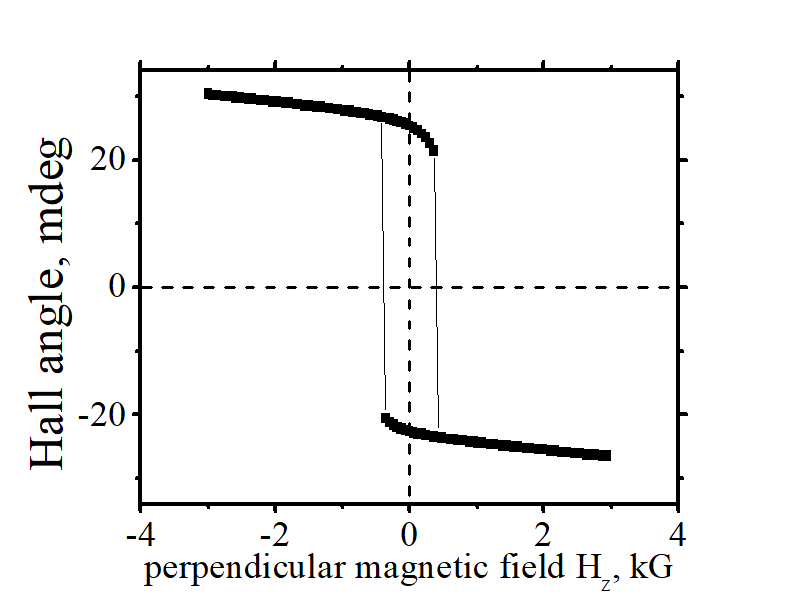
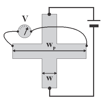
Influence of a Hall probe on a Hall measurement |
||||||
|---|---|---|---|---|---|---|
|
||||||
| click on image to enlarge it |
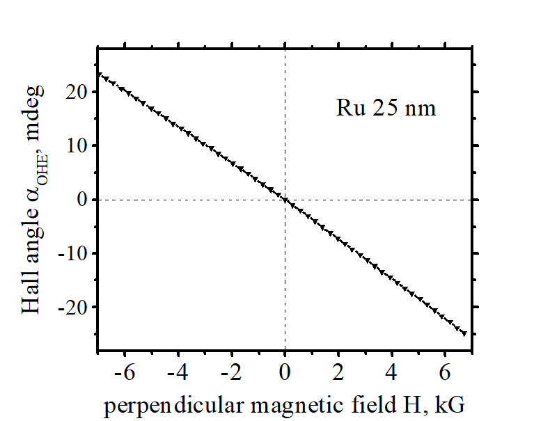
The Hall voltage VHall is linearly proportional to the width w of nanowire ( ![]() See HallAMRbasic.pdf)
See HallAMRbasic.pdf)
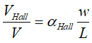
where V is the voltage applied to the nanowire, αHall is the Hall angle, which is a material parameter, w is the width and L is the length of the nanowire.
Fig.10a shows a conventional structure for a Hall measurement in a metallic nanowire. Two metallic contact (probes) contact the opposite sides of the nanowire to measure Hall voltage. However, the effective width at the measurement point is wider than the nanowire width w. The effective width wp also includes the length of the probe. It may cause a systematic error in the measurement of the Hall angle αHall ![]()
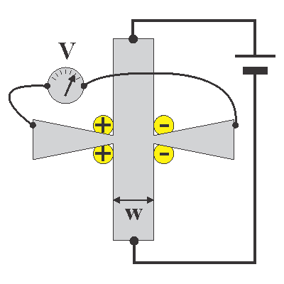
Fig.10b shows an optimized design with a Hall probes, which are narrowing near contact. In this case, the charge is accumulated at the contacts and a possible systematic error is minimized.
Usually, the width of Hall probe about 1-2 mm is still OK but critical. The maximum- allowed width strongly depends on the sample structure.
![]() There are several designs of Hall bars, which nearly fully exclude the undesired influence of the Hall probe.
There are several designs of Hall bars, which nearly fully exclude the undesired influence of the Hall probe.
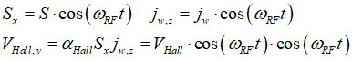
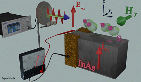
(main idea): ![]() The sample is illuminated by microwave at frequency of the Ferromagnetic resonance (FMR). The microwave excites the spin precession and additionally the microwave excites the electrical current. Since the Hall voltage proportional to both the spin direction and the current, which are both modulated by microwave, there are frequency beating of these two contribution. As a result, there is a DC component of the Hall voltage which is measured.
The sample is illuminated by microwave at frequency of the Ferromagnetic resonance (FMR). The microwave excites the spin precession and additionally the microwave excites the electrical current. Since the Hall voltage proportional to both the spin direction and the current, which are both modulated by microwave, there are frequency beating of these two contribution. As a result, there is a DC component of the Hall voltage which is measured.
(merit of the method):  It is possible to separate a studied Hall contribution from other contribution and measure a really weak Hall effect. For example, it is possible to measure a very weak ISHE effect in a paramagnetic metal.
(what is modulated by RF):![]()
![]() spin direction;
spin direction; ![]() electrical current
electrical current
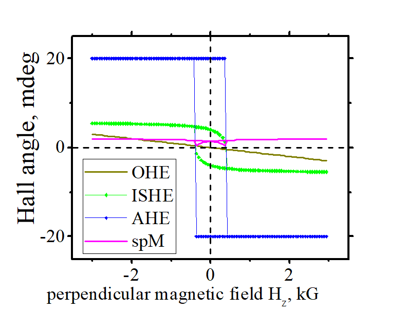
RF measurement of Inverse-Spin Hall effect (ISHE) in a nonmagnetic material |
||||||||||||||||||||||||||
|---|---|---|---|---|---|---|---|---|---|---|---|---|---|---|---|---|---|---|---|---|---|---|---|---|---|---|
|
||||||||||||||||||||||||||
| click on image to enlarge it |
(what is modulated by RF):![]()
![]() spin direction of localized d- electrons;
spin direction of localized d- electrons; ![]() spin direction of conduction electrons
spin direction of conduction electrons
types of the Hall effect |
||||||||||||||||||||||||||||
|
||||||||||||||||||||||||||||
| click on image to enlarge it. Zayets 2020.03 |
types of the Hall effect |
||||||||||||
|
||||||||||||
| Figure shows the side- jump scatterings in the electrical field of a defect as an example. Any mechanism of spin-dependent scatterings contributes to these effects: mechanism 1, Skew scatterings (mechanism 2), side- jump scatterings (mechanism 4, mechanism 5) | ||||||||||||
| click on image to enlarge it |
There is no relation between AMR/PHE and AHE.
From an experiment, this fact is known for a while. See, for example, T.R. Mcguire and R.I. Potter, IEEE Trans. Magn. (1975).
From theory point of view, the AMR/PHE and AHE have different symmetries and different physical origins. Therefore, they are two very different effects.
Difference 1: difference in the symmetry
The AHE is a linear magneto-transport effect. The AMR/PHE is a second- order magneto-transport effect. In a nanomagnet there are 3 independent variables, which time-inverse symmetry is broken: (1) externally-applied magnetic field H; (2) the total spin Sd of localized d- electrons (or the magnetization M) and (3) the total spin Scond of the spin-polarized conduction electrons (or the spin polarization). A linear magneto-transport effect is linearly proportional either to H or Sd or Scond. The ordinary Hall effect is proportional to H. The AHE is linearly proportional to Sd. The inverse spin Hall effect (ISHE) is linearly proportional to Scond. A 2nd order magneto-transport effect is proportional to a product of a pair from H, Sd and Scond. Additionally to the AMR/PHE, the in-plane GMR is also a 2nd order magneto-transport effect.
Difference 2: difference in the physical origin.
The AHE is dependent only on the magnetization (Sd) and is independent of spin polarization of the conduction electrons (Scond). In contrast, the AMR/PHE depends on both the magnetization and the spin polarization. The origin of the AHE is the spin-dependent scatterings of conduction electrons, which depend on the spin of a d- electron, but is irrelevant to the spin of a conduction electrons. The origin of the AMR/PHE is also spin-dependent scatterings of conduction electrons, but of different type, which depend on the angle between spin of a d- electron and the spin of a conduction electron.
A 1st order magneto-transport effect (Anomalous Hall effect, Inverse Spin Hall effect & Ordinary Hall effect) can be easily distinguished experimentally from a 2nd order magento-transport effect (AMR/PHE, in-plane GMR etc.). Since the 1st order magneto-transport effect is linearly proportional to magnetization M + external magnetic field H, it reverses its polarity when H+M are reversed. In contrast, the 2nd order magento-transport effect is proportional to a square/product of magnetization M + external magnetic field H, it does not reverse its polarity when H+M are reversed.
It is a common rule for any magneto-transport measurement that two measurements are always done with the magnetization in the forward and reversed direction. Next, the symmetric and antisymmetric contributions of measurements are calculated. The anisymmerical contribution is associated with the 1st order magneto-transport effects and the symmerical contribution is associated with the 2st order magneto-transport effects. In this way any unwanted contribution of 1st order magneto-transport effects to a measurement of a 2st order magneto-transport effect can be avoided and vice versa.
As an example see my AMR/PHE measurement for nanomagnets here.
![]()
![]() I am strongly against a fake and "highlight" research
I am strongly against a fake and "highlight" research ![]()
![]()
![]()
![]()
![]()
![]()
I will try to answer your questions as soon as possible


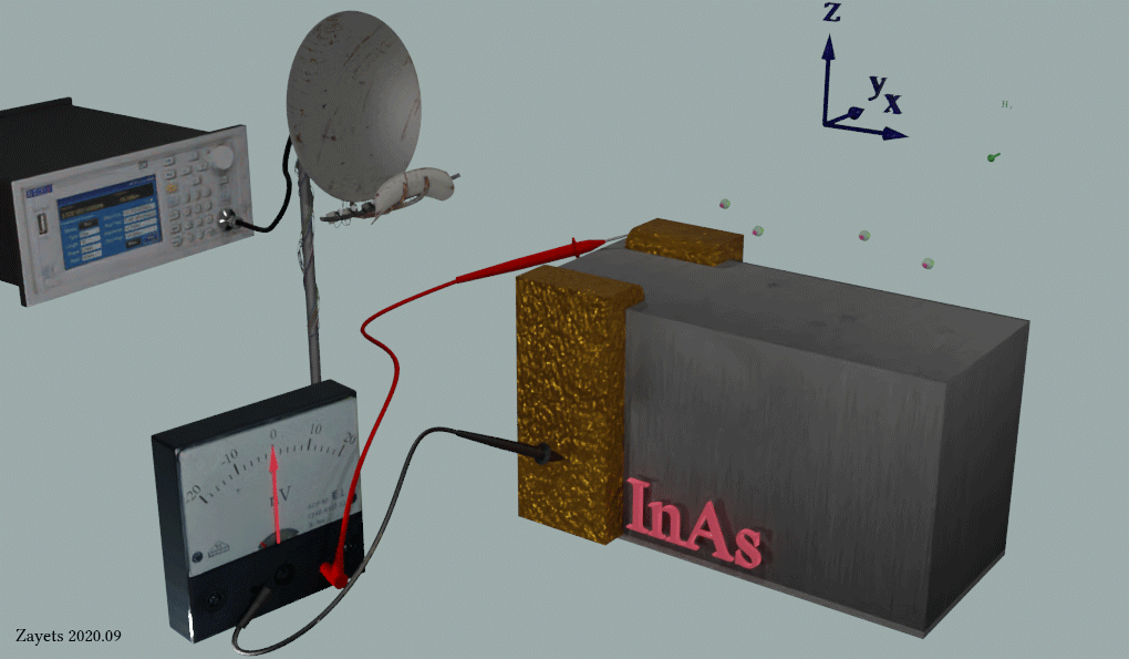
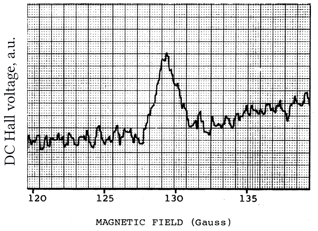
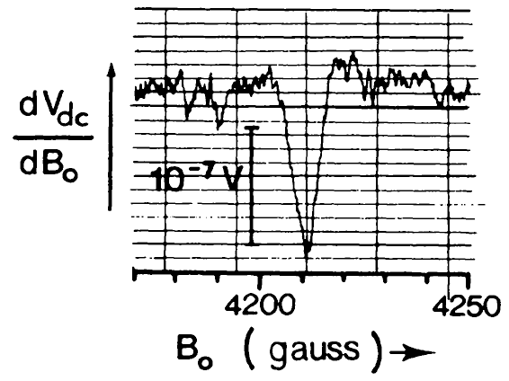
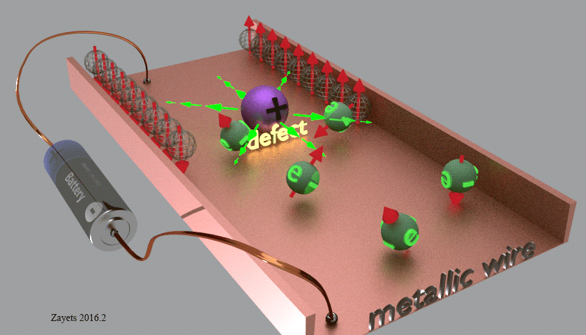
 A nonmagnetic InAs is illuminated by RF microwave radiation (blue/ green wave).The microwave radiation is produced by the RF generator (left-upper box) and the microwave antenna. The microwave RF radiation produces a Hall voltage, which is measured by the nanovoltmeter. Two metallic contact on the bulk InAs are used to measure DC Hall voltage.