Dr. Vadym Zayets
v.zayets(at)gmail.com
My Research and Inventions
click here to see all content |

Dr. Vadym Zayetsv.zayets(at)gmail.com |
|
|
more Chapters on this topic:IntroductionTransport Eqs.Spin Proximity/ Spin InjectionSpin DetectionBoltzmann Eqs.Band currentScattering currentMean-free pathCurrent near InterfaceOrdinary Hall effectAnomalous Hall effect, AMR effectSpin-Orbit interactionSpin Hall effectNon-local Spin DetectionLandau -Lifshitz equationExchange interactionsp-d exchange interactionCoercive fieldPerpendicular magnetic anisotropy (PMA)Voltage- controlled magnetism (VCMA effect)All-metal transistorSpin-orbit torque (SO torque)What is a hole?spin polarizationCharge accumulationMgO-based MTJMagneto-opticsSpin vs Orbital momentWhat is the Spin?model comparisonQuestions & AnswersEB nanotechnologyReticle 11
|
Method of zero- harmonic. RF measurements of magneto-transport effects. Ferromagnetic resonance. Spin and Charge TransportAbstract:In this method, the spin precession (e.g. Ferromagnetic resonance (FMR) ) is excited by illumination of sample by RF radiation. At resonance conditions, there is a magnetization precession and the magnetization direction changes with the RF frequency. It modulates the magneto- transport feature (e.g. Hall angle or magneto- resistance). In the case, when an additional magneto- transport parameter (for example, current) is modulated by the RF radiation, the frequency beating gives DC voltage, which is proportional to RF power. In this method, the features of the magneto-transport are evaluated from the DC voltage.Content
() Ferromagnetic 6. Explaination video
(main idea):
(merit of the method):
(Method 1).
|
RF measurement of Inverse-Spin Hall effect (ISHE) in a nonmagnetic material |
||||||||||||||||||||||||||
|---|---|---|---|---|---|---|---|---|---|---|---|---|---|---|---|---|---|---|---|---|---|---|---|---|---|---|
|
||||||||||||||||||||||||||
| click on image to enlarge it |
(How does it work?) Microwave RF radiation excites RF current in the sample. When RF frequency is close to the frequency of ferromagnetic resonance (FMR), the microwave excites the spin precession of both the localized d- electrons and spin-polarized- conduction electrons. The current experience the AHE effect due to the spin of localized electrons and the ISHE due to the spin of conduction electrons. Due to frequency beating between the RF- modulated spin and the RF - modulated current, there id a DC component of Hall voltage, which is measured.
 Geometry of measurement
(requirement 1): The directions of Hall probe, current and magnetization vibration should all be perpendicular each other.
Since the magnetization does not change its magnitude but only direction, its parallel M|| and perpendicular M⊥ components are:
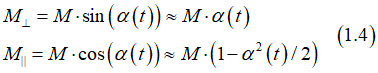
where ![]()
α is magnetization angle.
Therefore, the change of the perpendicular component M⊥ of the magnetization is only contribute to the measurement.
(only possible geometry:) The Hall bar is perpendicular to current. The magnetization either along the current or the Hall bar or in their common plane
E.g. current j|| is along x-direction, the Hall probe is along the y-direction and is M⊥along z-direction. It is possible only when the magnetization is along x- or y- directions
 Importance of phase matching between magnetization vibrations and current
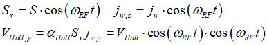
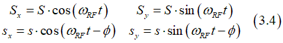
For this measurement it is important to match the phase of current to the magnetization vibration. For example, if current is along x-axis and change of magnetization is along z- axis and the Hall probe is along y- axis:
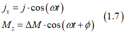
where φ is phase difference difference between oscillations of the magnetization and current.
The Hall angle is calculated as
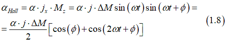
where α is the Hall angle of the material
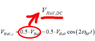
The zero harmonic is calculated
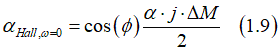
![]() The zero harmonic has maximum and is positive at φ=0 deg; has maximum and is negative at φ=180 deg; and it is zero at φ=90 and 270 deg;
The zero harmonic has maximum and is positive at φ=0 deg; has maximum and is negative at φ=180 deg; and it is zero at φ=90 and 270 deg;
(what is modulated by RF):![]()
![]() spins of localized d- electrons;
spins of localized d- electrons; ![]() spins of spin-polarized conduction electrons
spins of spin-polarized conduction electrons
(where it is used) ferromagnetic materials. Only in a ferromagnetic material both the total spin of conduction electrons and the total spin of localized electrons are non-zero.
(How does it work?)Microwave RF radiation excites a spin precession. The frequency beating of the RF- oscillating components of spins of localized d- electrons and conduction electrons gives the a DC current, which is measured.
Let us consider the case when a DC current flows along the x-direction and the Hall probe is along the y-direction. The effects, which can be detected by the RF technique, depends on the direction of the magnetic field with the direction of the electrical current.
RF measurement of 2nfd order magneto-transport effects |
||||||
|---|---|---|---|---|---|---|
|
||||||
| DC voltage in Fe is applied to nanowire and a DC current flowing through the FE nanomagnet. | ||||||
| click on image to enlarge it |
 Magnetic field is perpendicular to the current and the Hall bar
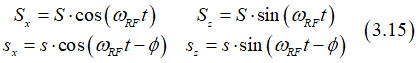
 For spin S directed along the z-axis, the spin precession is describes as
where S is spin component in the xy-plane.
According to he AMR/ Planar Hall effect (Kondo type), the spin creates a current (See here), which is described as
![]()
where S is the total spin of localized d- electrons and s is the total spin of the spin- polarized conduction electrons.
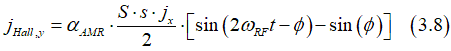
In the case when the a Hall probe is in the y- direction, the measured Hall voltage is created by the y- component of the current jmag, which is calculated as
![]()
Substitution of Eq.(3.4) into (3.6) gives
![]()
or
The DC- component (the non- oscillating component) of Hall current is calculated as
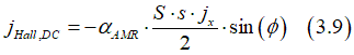
(note):![]() There is a DC Hall voltage when there is a non-zero time leg between the precession of conduction and localized electrons.
There is a DC Hall voltage when there is a non-zero time leg between the precession of conduction and localized electrons.
The effect of the Anisotropic Magneto Resistance (AMR) describes the magnetically- created current jmag (Eq. 3.5) flowing along the bias current jx. It can be calculated as
![]()
Substitution of Eq.(3.4) into (3.10) gives
![]()
or
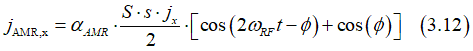
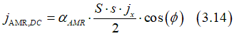
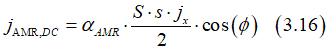
The DC- component (the non- oscillating component) of AMR current is calculated as
Magnetic field is perpendicular to the current and is along the the Hall bar
For spin S directed along the y-axis, the spin precession is describes as
 There is no DC current of the Planar Hall effect for this geometry
From Eqs (3.10)(3.15) The DC- component (the non- oscillating component) of AMR current is calculated as
Magnetic field is along to the current and is perpendicular the the Hall barFor spin S directed along the x-axis, the spin precession is describes as
There is no DC current of the Planar Hall effect for this geometry
There is no DC current for the AMR effect for this geometry
 Measurement of time leg between spin precession of conduction and localized d- electrons
(in an equilibrium) The spin directions of localized d-electrons and spin-polarized conduction electron are the same (See here). In a ferromagnetic metal, the conduction electrons are spin- polarized, because of the spin pumping. The electrons scattering are trying to disalign spins of conduction electrons. However, this disalignment mechanism (which is called the spin relaxation) is balanced by the spin pumping (See here). The spin pumping is the mechanism of alignment of spins of conduction electrons along the spins of the localized electrons due to the sp-d exchange interaction and the electron scatterings). Naturally, the spins of localized and spin-polarized conduction electrons are aligned in one direction.
(spin rotation) The spin of conduction electrons aligns to the spin of localized electron fast, but not infinitely fast. When the spin direction of localized
Dependence of detected DC voltage on time lag (time delay) between precessions of conduction and localized d-electrons |
||||||
|---|---|---|---|---|---|---|
|
||||||
| click on image to enlarge it |
(influence 1) ![]() The close the microwave frequency to the FMR frequency, the more efficient the excitation of precession of spins of localized d-electrons and therefore the angle of spin precession becomes larger.
The close the microwave frequency to the FMR frequency, the more efficient the excitation of precession of spins of localized d-electrons and therefore the angle of spin precession becomes larger.
(influence 2) ![]() The close the microwave frequency to the FMR frequency, the large the time leg φ between precession of localized d- electrons and conduction electrons. It enhances 2nd order magneto-transport effects, for example, the Planar Hall effect (See above)
The close the microwave frequency to the FMR frequency, the large the time leg φ between precession of localized d- electrons and conduction electrons. It enhances 2nd order magneto-transport effects, for example, the Planar Hall effect (See above)
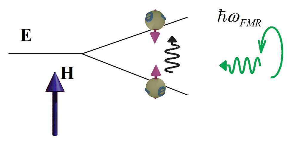
Excitation of FMR. Quantuum mechanical type |
|
| Quantuum mechanical type of excitatation of FMR resonance. A curculary polarized electromagnetic wave (shown in green) excites the electron from the lower energy spin- up state to the higher- energy spin- down state |
| In a magnetic filed H, the energy of level of an electron is splitted into two (the Zeemann splitting). Energy of electron with spin parralel to the magnetic field |
| Because only a part of spin-up electrons are excited into the spin- down state, the total spin (the sum of all spin-up and spin- down spins) gives spin, which is at an angle to H and the there is the pression of the total spin around H. |
| click on image to enlarge |
The ferromagnetic resonance (FMR) is the spin precesion under illumination of a nanomagnet by microwave at frequence close to the Larmor frequency.
(note)
Parametric excitation of Ferromagnetic resonance |
|
| Resonance enhancment of the FMR by linearly polarized electromagnetic wave. |
| green ball shows the magnetization. |
| click on image to enlarge it |
By circulary polarized microwave.
In this case the spin is transfered from a photon to the manetization of the nanomagnet.
(polarization of RF field)  FMR is excired by a linerally- polarized electromagnetic wave.
(geometry of FMR experiment) Magnetic field of the electromagnetic wave is pependicular to the easy axis of smaple (nanomagnet). It means that the linear polarization of microwave is parallel of the easy axis or the propagation direction of the microwave is
In this case an alternating magnetic of microwave dis align mgnetization spin with respect to the internal (external) magnetic field
By electrical current.
In this case an alternating magnetic of microwave dis align mgnetization spin with respect to the internal (external) magnetic field
![]() When a very large magnetic field is applied, the magnetization of the nanomagnet is aligned along the field.
When a very large magnetic field is applied, the magnetization of the nanomagnet is aligned along the field.
![]() However, when the magnetic field is weak or moderate, the magnetization is aligned between directions of the easy axis of the nanomagnet and the magnetic field
However, when the magnetic field is weak or moderate, the magnetization is aligned between directions of the easy axis of the nanomagnet and the magnetic field
![]() Each nanomagnet has a magnetic anisotropy and therefore there are the easy and hard axis for any nanomagnet. In absence of an external magnetic field, the magnetization is aligned along the easy axis. In order to align the magnetization along the hard axis, an external magnetic field field should be applied along the hard axis and therefore perpendicularly to the easy axis. The minimum field, at which the magnetization is aligned along the hard axis, is called the anisotropy field Hani. (see here and here). The feature of the magnetic anisotropy is that the magnetization component Mx along hard axis is linearly proportional to the component of applied magnetic field Hx along this direction (see here)
Each nanomagnet has a magnetic anisotropy and therefore there are the easy and hard axis for any nanomagnet. In absence of an external magnetic field, the magnetization is aligned along the easy axis. In order to align the magnetization along the hard axis, an external magnetic field field should be applied along the hard axis and therefore perpendicularly to the easy axis. The minimum field, at which the magnetization is aligned along the hard axis, is called the anisotropy field Hani. (see here and here). The feature of the magnetic anisotropy is that the magnetization component Mx along hard axis is linearly proportional to the component of applied magnetic field Hx along this direction (see here)
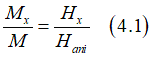
Then, the angle α of magnetization with respect to its easy axis is calculated as
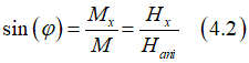
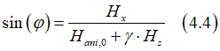
The anisotropy field Hani also depends on the component of magnetic filed Hz applied along easy axis (see here). The dependence can be approximated roughly as linear.
![]()
At very large magnetic field Hz, γ approaches 1 and the magnetization is aligned along the external magnetic field. Substitution of Eq.(4.3) into Eq.(4.2) gives the magnetization angle as
 Ferromagnetic resonance (FMR)
FMR of nanomagnet with PMA under in-plane magnetic field |
 |
Without an external magnetic, the magnetization M is perpendicular to the film due to PMA. When external in-plane magnetic field Hext is applied, the magnetization turns. The magnetic field , at which the magnetization turns fully in-plane is called the anisotropy field |
| Click on image to enlarge it |
 Video
Video 
Parametric magnetization reversal. Spin- orbit torque Conference presentation. Intermag 2021 |
|---|
![]()
![]() I am strongly against a fake and "highlight" research
I am strongly against a fake and "highlight" research ![]()
![]()
![]()
![]()
![]()
![]()
I will try to answer your questions as soon as possible

 It is possible to separate a studied Hall contribution from other contribution and measure a really weak Hall effect. For example, it is possible to measure a very weak ISHE effect in a paramagnetic metal.
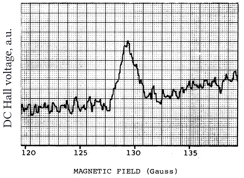
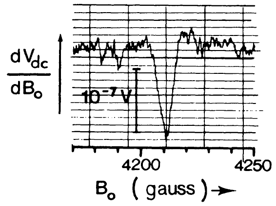
 A nonmagnetic InAs is illuminated by RF microwave radiation (blue/ green wave).The microwave radiation is produced by the RF generator (left-upper box) and the microwave antenna. The microwave RF radiation produces a Hall voltage, which is measured by the nano- voltmeter. Two metallic contact on the bulk InAs are used to measure DC Hall voltage.