Dr. Vadym Zayets
v.zayets(at)gmail.com
My Research and Inventions
click here to see all content |

Dr. Vadym Zayetsv.zayets(at)gmail.com |
|
|
more Chapters on this topic:IntroductionTransport Eqs.Spin Proximity/ Spin InjectionSpin DetectionBoltzmann Eqs.Band currentScattering currentMean-free pathCurrent near InterfaceOrdinary Hall effectAnomalous Hall effect, AMR effectSpin-Orbit interactionSpin Hall effectNon-local Spin DetectionLandau -Lifshitz equationExchange interactionsp-d exchange interactionCoercive fieldPerpendicular magnetic anisotropy (PMA)Voltage- controlled magnetism (VCMA effect)All-metal transistorSpin-orbit torque (SO torque)What is a hole?spin polarizationCharge accumulationMgO-based MTJMagneto-opticsSpin vs Orbital momentWhat is the Spin?model comparisonQuestions & AnswersEB nanotechnologyReticle 11
|
Anisotropic magnetoresistance (AMR) and Planar Hall effect. Spin and Charge TransportAbstract:The Anisotropic magnetoresistance (AMR) describes a change of resistance of ferromagnetic wire, when its magnetization change its direction with respect to current direction. The Planar Hall effect describes a generation of a Hall current perpendicularly to bias current, when the magnetization is at 45 degrees between the electron current and Hall probe.The AMR and the Planar Hall effect describe one single odd magneto-transport effect, which describe magnetic generation of a current flowing along the magnetization direction.
|
Two features of one effect: Anisotropic magneto- resistance & Planar Hall effect |
|---|
 |
| FeB nanomagnet on top of tantalum (Ta) nanowire. A Hall probe is aligned to the nanomagnet. The nanovoltmeter (at the left) measures the Hall voltage and resister meter (at the right) measures the total resistance. The FeB magnetization (green ball) is in-plane. Direction of external in-plane magnetic field H|| (green arrow) is rotating. The magnetization follows the H|| rotation. There is a electron current jV flowing through the nanomagnet. |
| jM is magnetically- generated current, which direction is along (or opposite) to magnetization direction and which magnitude is proportional magnetization component along current. |
| AMR effect due to jM component || current jV. When magnetization || to wire, is opposite to and wire resistance increases. When magnetization ⊥ to jV , jM =0 and wire resistance is smaller. |
| Planar Hall effect due to jM component ⊥ current jV. The perpendicular component of jM and therefore Hall voltage is largest when magnetization is at 45 deg. with respect to jV |
| click on image to enlarge it |
The effect of the anisotropy magnetoresistance describes the fact the resistance of a ferromagnetic metal becomes smaller, when the magnetization of the metal changes from parallel to perpendicular direction in the respect to the direction of the electrical current flowing in the metal. Spin- dependent scatterings originate this effect.
The Planar Hall effect is a Hall voltage created when magnetization is in-plane (in one plane with current and Hall probe. . It is largest when at 45 degrees with respect to current direction and Hall probe.
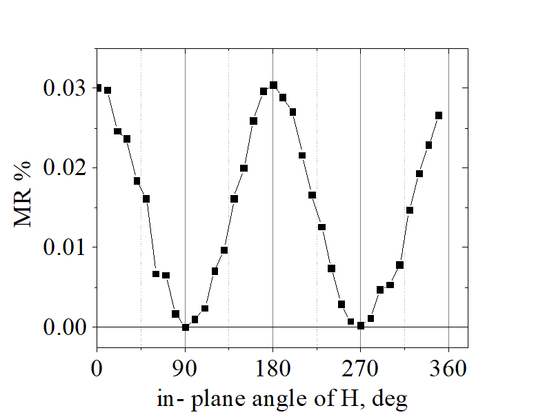
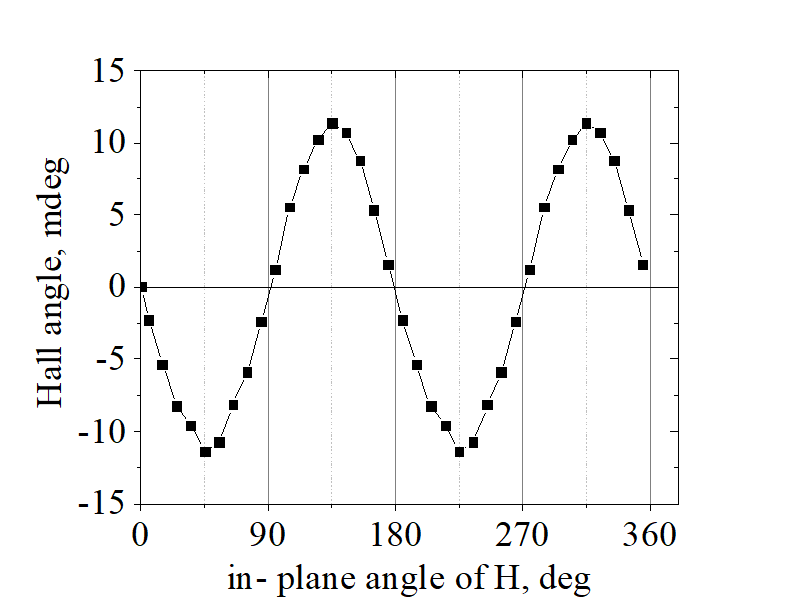
(measurements):  Both the AMR and the Planar Hall effect are measured by rotating magnetization in-plane. Usually, the resistance is highest when magnetization is parallel to the current and is lowest when magnetization is perpendicular to the current. The Hall voltage is largest when angle between current and magnetization is 45 degrees. There is no Hall voltage, when magnetization is either parallel or perpendicular to the current.
(another measurement) The magnetization also can be rotated from perpendicular to plane direction to parallel-to current direction, Similarly, the resistance is highest when magnetization is parallel to the current. There is no Planar Hall effect (there is no Hall voltage) in case of such rotation.
| Anisotropic Magneto Resistance (AMR) & Planar Hall effect (PHE) | ||||||||||||
|---|---|---|---|---|---|---|---|---|---|---|---|---|
|
||||||||||||
| Sample Volt 54a R13C (see here about sample details) | ||||||||||||
| click on image to enlarge it |
AMR+ Planar Hall effect is an even magneto- transport effect (see here), which polarity is not reversed when direction of a substantially substantially large magnetic field is reversed.
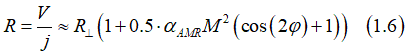
Both the AMR and the Planar Hall effects are described by one equation, which is describes the magnetically- created current jM as:
![]()
where is jv the conventional electron current flowing through metallic wire from source to drain, αAMR is AMR coefficient or AMR angle., M is the magnetization
The projection of jM parallel to jv describes the AMR effect:
![]()
The projection of jM perpendicularly to jv describes the AMR effect:
![]()
where φ is the angle between magnetization M and current jv.
The total flowing through the wire is a sum of and :
![]()
The current is largest and therefore the wire resistance is smallest when M perpendicular to the wire (φ =+90o or -90o). In this case, jAMR=0 and j=jM.
The current is smallest and therefore the wire resistance is largest when M parallel to the wire (φ =+90o or -90o). In this case
![]()
The wire resistance is
It is largest, when M parallel to the wire:
![]()
The AMR ratio is define as relative change of resistance when the magnetization is rotated from to be parallel to to be perpendicular with respect to current direction
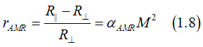
The resistance vs. φ can be calculated as
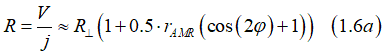
or
![]()
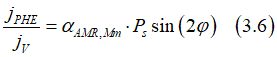
The Hall voltage VHall. for the Planar Hall effect is calculate as (see here)
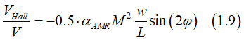
The magnitude of Hall voltage is largest VHall, when magnetization M is at 45 degrees with respect to current jv (φ =+45o or -45o or 180o+45oor 180o-45o). VHall is positive at -45o and 180o-45o and negative at +45o and 180o+45o. VHall=0 at φ =0o; +90o; -90o; 180o
The Hall angle θPH for the Planar Hall effect is calculate as
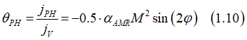
The maximum Hall angle at φ =+45o; -45o; 180o+45o;180o-45o is calculated as
![]()
The Hall angle θPH for the Planar Hall effect vs φ is calculate as
![]()
 |
| click on image to enlarge it |
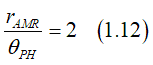
Comparison of Eq.1.8 and Eq.1.11 gives
A direction measurement from the resistance change often contains a systematic error due to the contact resistance and the nanowire resistance. In contrast, the benefit of the AMR measurement from the Planar Hall effect benefits of a locality of measurement and independence from contact and wire resistances .
 Measurement of AMR
(bulk material):![]() By a measurement of change of resistance when magnetization changed from perpendicular to parallel direction with respect to electrical current.
By a measurement of change of resistance when magnetization changed from perpendicular to parallel direction with respect to electrical current.
(a nanomagnet):![]() From a measurement of the Planar Hall effect. The resistance of nanomagnet is substantialy smaller than a parastic resistance of nawire and contacts. It makes unreliable the evaluation of the AMR from the resistivity change.
From a measurement of the Planar Hall effect. The resistance of nanomagnet is substantialy smaller than a parastic resistance of nawire and contacts. It makes unreliable the evaluation of the AMR from the resistivity change.
| AMR in ferromagnetic metals | ||||||
|---|---|---|---|---|---|---|
|
||||||
|
||||||
| click on image to enlartge it |
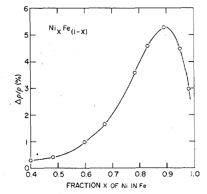
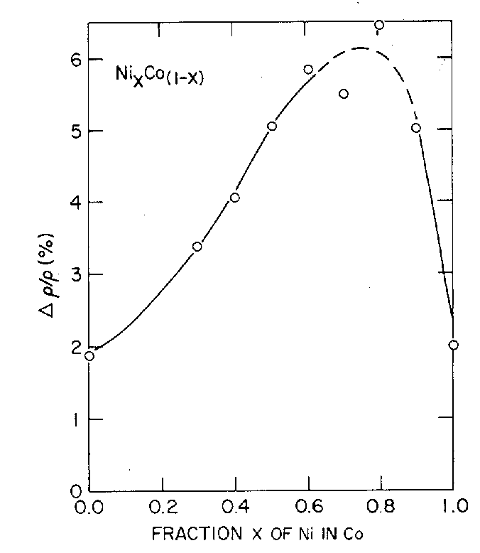
The AMR is know to be high in nickel containg materials and can reach cose to 10%. In Fe and Co, the AMR is not as large, depends on device geometry and typically is smaller than 0.1 %.
(about a peak of AMR) ![]() There is a peak for dependence of the AMR on Ni content, where AMR has a maximum. For a long time it has not been understood why this content of Ni (~0.9) is so special for the AMR.
There is a peak for dependence of the AMR on Ni content, where AMR has a maximum. For a long time it has not been understood why this content of Ni (~0.9) is so special for the AMR.
The AMR effect is origanated from special spin- dependent scatterings, which depends on mutul spin direction of locolized and conduction electrons. Therefore, the scattering probability for spin- polarized conduction electrons is larger, for example, toward the left than towards right. It occurs due to influence of the spin of localized d-electrons on the strength of the spin- orbit interaction of the conduction electrons (See below). Such influence occurs only for a spific orbital configuration. The orbital of Ni is well matched t that condition and therefore the AMR in Ni is large. The orbitals of Fe and Co do not promote this kind of the spin-orbit interaction. As a result, the AMR is weak in Fe and Co.
The AMR linearly proportional to three paramenters: (parameter 1): total spin of localized d- electrons (magnetization); (parameter 2): the total spin of spin- polarized conduction electrons (spin polarization) ; (parameter 3): the probability of required spin- dependent scattering. In Ni, the probability of the spin- dependent scatterings is high, but both the spin polarization and magnetization are small. Adding some Fe or Co to Ni increases the spin polarization and the magnetization, which leads to an increase of the AMR. At the same time, the adding of Fe or Co reduces the probability of the required spin-dependent scatterings, which leads to a decrease of the AMR. There is an optimum Ni concentration, at which the spin polarization and the magnetization are large enough, but the the probability of the spin-dependent scatterings is not reduced much.
 Origin of AMR & Planar Hall effect
(general notes):
(note 1) As a magento- transport effect, AMR/PHE is originated from spin- dependent scatterings of the conduction electrons.
(note 2) In a general case, the spin direction of spin-polarized conduction electrons and localized electrons are the same, which is the magnetization direction
(note 3) The current jAMR/PHE of the AMR/PHE effect flows along the magnetization direction.
There are 3 contributions to AMR/PHE effect:
![]() (contribution 1): Kondo- type contribution
(contribution 1): Kondo- type contribution ![]() ⇔
⇔ ![]()
It is the main contribution. The contribution is due to a scattering of the spin-polarized conduction electron on the localized electrons and which is proportional to mutual direction of spins of the localized and spin-polarized conduction electrons. The current jAMR/PHE of the AMR/PHE effect can be described as:
![]()
where j is the electron current, Slocal is the total spin of the localized electrons, Scond is the total spin of the conduction electrons.
![]() (contribution 2): 2nd-AHE-like contribution
(contribution 2): 2nd-AHE-like contribution ![]() ⇔
⇔ ![]()
The contribution is proportional to the spin of the localized electrons Slocal, but is independent of the spin of the conduction electrons Scond .
![]()
The symmetry of this contribution is the same as if the current experience twice the Anomalous Hall effect (AHE). In fact, the Hall current cannot experience AHE second time due to the geometrical restriction (see below). However, spin-dependent scatterings may have similar symmetry.
![]() (contribution 3): 2nd- ISHE-like contribution
(contribution 3): 2nd- ISHE-like contribution ![]() ⇔
⇔![]()
The contribution is proportional to the spin of the conduction electrons Scond , but is independent of the spin of the localized electrons Slocal.
![]()
The symmetry of this contribution is the same as if the current experiences twice the Inverse Spin Hall effect (ISHE). Simalary, the Hall current cannot experience ISHE second time due to the geometrical restriction (see below). However, spin-dependent scatterings may have similar symmetry.
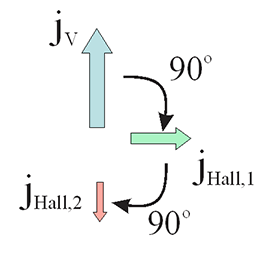
 Classical incorrect origin of AMR: Two consequent Hall rotations.
The AMR effect and the effect of Planar Hall resistance can be explained as two consequent Hall rotations as follows
 AMR as two consequent Hall rotation. (Incorrect suggestion) AMR as two consequent Hall rotation. (Incorrect suggestion) |
|||||||||
|---|---|---|---|---|---|---|---|---|---|
|
|||||||||
When magnetic field H (or magnetization M) is perpendicular to bias current jV, there is a Hall current jHall flowing perpendicularly to jV
![]()
The Hall current jHall flows perpendicularly to H and therefore itself experience the Hall effect. The second Hall current jHall,2 can be calculated as
![]()
using the vector relation
![]()
The Eq. (2.3) is simplified as
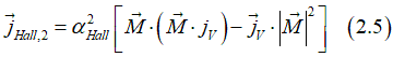
The first term of Eq. (2.5) describes the AMR and Planar Hall effects:
![]()
The second terms of Eq. (2.5) describes the direction-independent magneto-transport effect
![]()
Eq 2.6 became same as
![]()
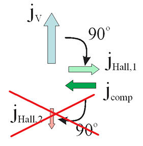
A. This explaination requires a flow of electron current perpendicularly to the wire. However, there is no such a current. The Hall current jHall is fully ballanced the opposite current, which is induced by the Hall voltage. As there is no perpendicular current, there is no secondary Hall effect.
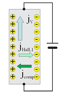
Any electron current, which flows perpendicularly to a metallic wire, creates a charge accumulation on sides of the wire. A balance current flows opposite to the Hall current. Therefore, in total there is no current, which flows perpendicularly to the wire, the balance current fully compensate the Hall current and the second Hall current cannot be created.

As can be seen from Eq.2.8, the experimentally observed AMR is opposite to that expected from two consequent Hall effects. When magnetization is perpendicular to the current, there is Hall effect, two 90 deg rotations makes the 2nd Hall current flowing opposite to the main current and therefore the resistance should increase. Experimentally observed dependence is opposite (See Fig.), the resistance is largest when the magnetization is parallel to the current.
(note) ![]() Even though the two consequent Hall rotations is not origin of the AMR effect, it give all correct description of all even magneto transport effect The first term in Eq.2.5 describes the AHE + Planar Hall effect. The second term describes the spin- dependent conductivity.
Even though the two consequent Hall rotations is not origin of the AMR effect, it give all correct description of all even magneto transport effect The first term in Eq.2.5 describes the AHE + Planar Hall effect. The second term describes the spin- dependent conductivity.
(note about wire capacitance) ![]() in the case of an AC current, the charge accumulation on the sides of wire are modulated and therefore the current jHall,1 is not fully balanced by jbalanc and jHall.2 exists. As a result, the two consequent Hall effects to MNR effect in the case of an AC current.
in the case of an AC current, the charge accumulation on the sides of wire are modulated and therefore the current jHall,1 is not fully balanced by jbalanc and jHall.2 exists. As a result, the two consequent Hall effects to MNR effect in the case of an AC current.
 Family of AMR/Planar Hall effects
The AMR& Planar Hall effect is an even magneto- transport effect (See here). Any even magneto-transport effect should be described as a vector product of two vector sets: (H, Slocal,Sconduct )*(H, Slocal,Sconduct ), where H is external magnetic field, Slocal, is the total spin of localized electrons and Sconduct is the total spin of conduction electrons. Different vector product of these vectors defines a different type of the AMR& Planar Hall effect
 Kondo- type AMR/Planar Hall effect Kondo- type AMR/Planar Hall effect is originated from interaction of spin of localized electrons Slocal and spin of conduction electrons Sconduct. Kondo- type AMR/Planar Hall effect is linearly proportional to the spin polarization of conduction electrons.
The scattering of the spin-polarized conduction electrons on localized d-electrons produces an electron current jM.
The component of jM, which is along the wire and, therefore, parallel to the main current jV, is originating the AMR effect. When jM is parallel to jV, for a fixed applied voltage the total current increases meaning the wire resistance decreases. When jM is opposite to jV, the total current decreases meaning the wire resistance increases. Therefore, the magnetization- dependent current makes the resistance to become dependent on the magnetization direction, which is the effect called Anomalous Magneto-Resistance (AMR).
The component of jM, which is perpendicular to the wire and, therefore, perpendicular to the main current jV, is originating the Planar Hall effect (PHE) effect. When a current flows perpendicular to a wire, a charge is accumulated at side edges of the wire. The voltage of this accumulated charge is called the Hall voltage.
The current jM, which is due to a spin-dependent scattering of spin-polarized conduction electrons on the spins of the localized electrons, should be proportional to the total spin of localized electron Slocal, to the total spin of conduction electrons Sconduct and to the electron current jV. There are a few possible options when a vector jm can be represented as a linear product of 3 vectors.
Additionally, the scattering probability should symmetrically depend on the spins of localized and conduction electrons. The scattering only on mutual spin direction without any preferences for spin of the localized or conduction electrons. This condition reduces the possibility only to one option:
![]()
Since Sconduct is linearly proportional to spin polarization Ps and Slocal is a constant, Eq. (3.1) is simplified as
![]()
where unit vectors M and m are unit vectors in spin directions of conduction and localized electrons.
Assigning φ+Δ as angle between spin of localized electrons and current jV and φ-Δ as angle between spin of spin- polarized conduction electrons and current jV, the projection jAMR of magnetic current jVf, which flows along the wire and, therefore, parallel to the main current jV, and which defines the AMR effect, is calculated from Eq.(3.2) as

Therefore, the AMR current can be calculated as
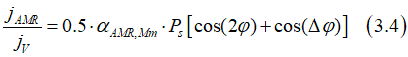
Except that the the AMR constant is linearly proportional to the spin polarization , the Kondo- type AMR effect is nearly the same as classical AMR (see Eq.1.2)
![]()
The Planar Hall effect is described by the perpendicular components of the magnetic current:

or
 Origin 1of Kondo- type AMR/Planar Hall effect: Spin-orbit interaction
Another Kondo-type magneto- transport effect is the Spin- dependent conductivity. This effect describes the Spin detection effect (See here) and the in-plane giant magnetic resistance (GMR) effect.
This Kondo-type magneto- transport effect is proportional to the scalar product of total spins of localized and conduction electrons:
![]()
Since this magnetic current is always along the main current jM || jV. the effect can be describe as a change of the total current
as in this case
![]()
or conductivity
![]()
if φ is the angle between the spin of localized electrons (magnetization) and the spin of conduction electrons and Ps is the spin polarization of the conduction electrons. The spin- dependent conductivity can be described as
The spin detection effect describes the creation of charge and voltage along diffusion path of a spin current. The origin of the spin- detection effect is the spin- dependent conductivity.
A spin diffusion current is a current of spin without a current of charge. It consists of two currents of spin-polarized and spin-unpolarized electrons, which flow in opposite directions. When
The effect of the spin- dependent conductivity does not contribute to the AMR or the Planar Hall effectThe spin
The spin
 spin- dependent conductivity is large at an interface
The spin
spin- dependent conductivity is large in a material with a low conductivityThe spin
AHE- like AMR/Planar Hall effect Two subsequent scatterings of spin- unpolarized conduction electronsAHE- like AMR/Planar Hall effect is proportional only to the total spin Slocal of localized d- electron (but not to the spin Scond of conduction electrons):
![]()
Since the total spin of localized d- electrons is along magnetization, the AHE- like contribution is calculated as
![]()
where M is an unit vector directed along magnetization.
(note) this contribution is independent of spin polarization of conduction electrons
(note) Both the spin- polarized and spin- unpolarized conduction electrons contribute to the AHE- like AMR/Planar Hall effect.
ISHE- like AMR/Planar Hall effect Two subsequent scatterings of spin- polarized conduction electronsISHE- like AMR/Planar Hall effect is proportional only to the total spin Scond of spin-polarized conduction electrons (but not to the spin Slocal localized d- electron):
![]()
Since Scond is linearly proportional to the number spin- polarized electrons and therefore to the spin polarization Ps, the ISHE- like AMR/Planar Hall effect is described as:
![]()
where M is an unit vector directed along magnetization
(note) this contribution is proportional to a square of spin polarization Ps of conduction electrons
(note): Only the spin- polarized conduction electrons contribute to the ISHE- like AMR/Planar Hall effect. The spin- unpolarized conduction electrons do not contribute
OHE- like AMR/Planar Hall effect The Lorentz force during Two subsequent scatterings of a conduction electronsIn this case the direction of magnetic current is along the direction of external magnetic field H
![]()
MH- type AMR/Planar Hall effect Simultaneously with a spin- dependent scattering an electron experiences the Lorentz force.It is a prominent feature of a magnetically- hard material (e.g. SmCo), in which the magnetization is firmly fixed along its easy direction and is nearly independent on external magnetic field H.
For this type, there is component (~Scond ), which is linearly proportional to the spin polarization and there is a component (~Slocal), which is independent of spin polarization Ps.
Additionally MH- type AMR/Planar Hall effect is divided into two additional types:
(type 1) in which magnetically-created current is parallel to the magnetic field: jM || H
![]()
(type 2) in which magnetically-created current is parallel to the magnetization: jM || M
![]()
AMR of FeB film |
Incorrect assumption that the Lorentz force is the origin the AMR effect |
 |
|
The resistance of FeB wire as function the angle between applied magnetic field and the direction of electrical current in the wire. 0 and 180 deg correspond to the case when magnetic field is along the wire. -90 and 90 deg correspond to the case when magnetic field is perpendicular to the wire and in film plane. AMR is about 0.09%. Important! The resistance becomes larger when the magnetic field is applied along the wire. This polarity of AMR is the same for the most of metal only with a few exceptions of some monocrystal metals. Sample Hall 16. Measured on 2016/02/29 |
When an electron moves between scatterings in an magnetic field, it experiences the Lorentz force. The Lorentz force turns out the electron from a straight path. Therefore, the magnetic field slows down the movement of the electron and the electrical resistance should increase when a magnetic field is applied perpendicularly to the electrical current. It is important: The metal resistance decreases when a magnetic field is applied perpendicularly to the wire (AMR effect) comparing to the case of no field or a field applied along the wire (See experimental measurements ). It is clear evidence that not the Lorentz force, but spin-dependent scatterings is origin of the AMR effect. |
Q. What is the difference between cases when magnetic field is applied along electron current or perpendicular to current?
Spin polarization of electron gas is along to the applied magnetic field. When magnetic field is perpendicular to the electron current, the scattering is spin-dependent and scattering probabilities towards left and right are different. When magnetic field is along the electron current, the scattering becomes spin-independent.
Q. Why the resistance of a metallic wire becomes larger when a magnetic field changes from perpendicular to parallel directions with respect to the direction of electrical current in the wire?
When magnetic field is perpendicular to electron movement, the scattering probability toward left ![]() and right
and right ![]() are different
are different![]() . In contrast when magnetic field is along to electron movement the scattering probability toward left
. In contrast when magnetic field is along to electron movement the scattering probability toward left![]() and right
and right![]() are same
are same![]() .
.
It is important that the total scattering probability are different for perpendicular![]() and parallel
and parallel ![]() directions of the magnetic field, because of the non-linear nature the Fermi-Dirac distribution. Usually
directions of the magnetic field, because of the non-linear nature the Fermi-Dirac distribution. Usually
![]()
and the metal resistivity is larger when magnetic field is along the electron current.
However, in some rare cases when there is a substantial energy dependence of the density of state at the Fermi surfers, the resistivity may be larger for a perpendicular magnetic field.
Q. The electrons in a metal move in all directions, why only electrons, which move along the electron current, contribute to the AMR effect?
A. All electrons contribute to the AMR effect. The contribution of the electrons, which move in the opposite directions, are of opposite signs. Along electron current the number of electrons, which moves along and opposite current, are different and their contributions do not compensate each other.
Q. Is any correlations between the AMR effect and Anomalous Hall effect, the Spin Hall effect and Inverse Spin Hall effect?
A.
Kondo mechanism: Anisotropic magnetoresistance (AMR) due to orbital momentum of electron |
||||||
case 1: orbital moment parallel to electron moving direction |
||||||
|---|---|---|---|---|---|---|
|
||||||
case 2: orbital moment perpendicular to electron moving direction |
||||||
|
||||||
| Sphere of directional distribution of conduction electrons. The length of a vector from axis origin to sphere is proportional to the number of electrons moving in the vector direction. In absence of electrical current J, the sphere is symmetrical and an equal amount of conduction electron moving in any direction. When electrical current flows along y-axis, sphere is shifted towards positive y- direction and more electrons flow along positive y- direction than in opposite direction. | ||||||
| Red/ blue bars show amount of magnetic energy, which a conduction electron experience in magnetic field H (green arrow) of spin of localized electrons (violet ball with arrow). Rotating arrows show orbital moment of conduction electron. When spin of localized electrons is along orbital moment, the magnetic energy is largest (bar is fully red) and the scattering probability in that direction is higher. | ||||||
| The size of arrows in lift- top corner proportional to the scattering probability in shown direction | ||||||
| click on image to enlarge it |
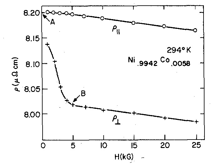
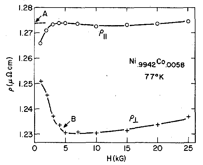
| AMR vs external magnetic field | |||||||||
|---|---|---|---|---|---|---|---|---|---|
|
|||||||||
|
|||||||||
| click on image to enlartge it |
There is no relation between AMR/PHE and AHE. At least, there is no a direct relation.
From an experiment, this fact is known for a while. See, for example, T.R. Mcguire and R.I. Potter, IEEE Trans. Magn. (1975).
From theory point of view, the AMR/PHE and AHE have different symmetries and different physical origins. Therefore, they are two very different effects.
Difference 1: difference in the symmetry
The AHE is a linear magneto-transport effect. The AMR/PHE is a second- order magneto-transport effect. In a nanomagnet there are 3 independent variables, which time-inverse symmetry is broken: (1) externally-applied magnetic field H; (2) the total spin Sd of localized d- electrons (or the magnetization M) and (3) the total spin Scond of the spin-polarized conduction electrons (or the spin polarization). A linear magneto-transport effect is linearly proportional either to H or Sd or Scond. The ordinary Hall effect is proportional to H. The AHE is linearly proportional to Sd. The inverse spin Hall effect (ISHE) is linearly proportional to Scond. A 2nd order magneto-transport effect is proportional to a product of a pair from H, Sd and Scond. Additionally to the AMR/PHE, the in-plane GMR is also a 2nd order magneto-transport effect.
Difference 2: difference in the physical origin.
The AHE is dependent only on the magnetization (Sd) and is independent of spin polarization of the conduction electrons (Scond). In contrast, the AMR/PHE depends on both the magnetization and the spin polarization. The origin of the AHE is the spin-dependent scatterings of conduction electrons, which depend on the spin of a d- electron, but is irrelevant to the spin of a conduction electrons. The origin of the AMR/PHE is also spin-dependent scatterings of conduction electrons, but of different type, which depend on the angle between spin of a d- electron and the spin of a conduction electron.
The following explanation might be slightly over simplified. I hope it will help you to grasp the main idea beyond the Planar Hall effect .
(PHE/AMR symmetry) The Planar Hall effect (PHE) and the Anomalous Magneto-resistance (AMR) are two features of one effect called in short PHE/AMR. The PHE/AMR is the second order magneto-transport effect, which means it is a vector product of the magnetization, electric current and the magnetization again. It means the magnetization is included twice into the vector product. It is why it is the 2nd order magneto-transport effect. The in-plane GMR is also the 2nd - order magneto transport effect and is a very close cousin of the PHE/AMR effect. The PHE/AMR effect depends on both the total spin of the localized electrons and the total spin of the conduction electrons (the spin- polarized conduction electrons to be exact). In an equilibrium, the spins of spin-polarized conduction electrons and the spins of the localized electrons are always parallel to each other (except for some specific cases) and it is simpler to describe both their direction by one vector, the magnetization. Once again, even though the PHE/AMR is proportional to the vector product of spins of localized and localized electrons, the magnetization is used twice in the formula for the PHE/AMR.
(Physical origin of the PHE/AMR) The origin of the PHE/AMR is the spin- dependent scattering of conduction electrons, which probability depends on mutual spin directions of conduction and localized electrons. It means that when the spin of a conduction electron is parallel to the spin of a localized electron, the probability of a scattering to the left is, for example, larger than the probability to the right. In contrast, when the spin of a conduction electron is opposite to the spin of a localized electron, the probability of a scattering to the left direction is smaller than the scattering probability to the right direction. Since the conduction electrons in a ferromagnetic metal are spin-polarized, there are more conduction electrons, whose spin is parallel to the total spin of the localized electrons (to the magnetization). As a result, in the total for all conduction electrons the probability of a scattering of a conduction electron towards the left direction is larger than the scattering probability towards the right direction. It results that the electrons are accumulated at the left side of a metallic wire and are depleted at the right side. It means the negative charge is accumulated/ depleted at the opposite sides of the wire and there is a Hall voltage due to this charge, which could be measured by a voltmeter. If one could reverse the spin direction of spin- polarized electrons opposite to the spin of the localized electrons by a spin injection, for example (it is very hard to do), the Hall voltage would change its polarity.
(Physical origin of the AMR) The origin of the AMR is very similar. When the magnetization is perpendicular to the current, the scattering to the left means the scattering along the current. Therefore, in this case the scattering probability for a conduction electron along the current is larger than the scattering probability opposite to the current. As a result, there are more electrons moving in the direction of the electron current, the conductivity becomes larger and correspondingly the resistance becomes smaller. When the magnetization is turned along current, there is no such difference in the scattering probability and, therefore, the resistance increases.As before, it is the case when the spin of a conduction electron is parallel to the spin of a localized electron. If one could reverse the spin direction of spin- polarized electrons opposite to the spin of the localized electrons, the polarity of the resistance change would be reversed.
A 1st order magneto-transport effect (Anomalous Hall effect, Inverse Spin Hall effect & Ordinary Hall effect) can be easily distinguished experimentally from a 2nd order magento-transport effect (AMR/PHE, in-plane GMR etc.). Since the 1st order magneto-transport effect is linearly proportional to magnetization M + external magnetic field H, it reverses its polarity when H+M are reversed. In contrast, the 2nd order magento-transport effect is proportional to a square/product of magnetization M + external magnetic field H, it does not reverse its polarity when H+M are reversed.
It is a common rule for any magneto-transport measurement that two measurements are always done with the magnetization in the forward and reversed direction. Next, the symmetric and antisymmetric contributions of measurements are calculated. The anisymmerical contribution is associated with the 1st order magneto-transport effects and the symmerical contribution is associated with the 2st order magneto-transport effects. In this way any unwanted contribution of 1st order magneto-transport effects to a measurement of a 2st order magneto-transport effect can be avoided and vice versa.
As an example see my AMR/PHE measurement for nanomagnets here.
A. I have never measured AMR in a ferromagnetic wire by myself and I can only suggest a possible problem. As far as I know, the measurement of the magneto-impedance is often used for a ferromagnetic wire. It is a very popular magnetic sensor. In fact, almost every cell phone has a ferromagnetic-wire sensor with a measurement of the magneto-impedance. The magneto- impedance is the complex resistance, which is measured at a RF frequency. I never heard that somebody has measured AMR in a ferromagnetic wire.
---------------- suggested problem
(problem 1: magnetic field is small) AMR is proportional to the magnetization direction, but not the applied magnetic field. Often a very large magnetic field is required to to turn the magnetization from its easy axis. E.g. a several- Tesla of magnetic field is required to turn magnetization of a thick Fe film from the in-plane to perpendicular-to-plane direction.
(problem 2: resistance is too small) For a reliable measurement of AMR, one should be able to reliably measure 0.01-0.1% change of resistance. For R=0.5 Ohm it is difficult. The contact resistance can be a problem. The heating can be a problem. The thermal resistance for your wire is not small. Reaching thermal stability can be difficult.
-------------------------
( As for the material and geometry:) AMR in some materials is very small. There is a bulk contribution and there is an interface contribution to AMR. Therefore, there is a geometry dependence for AMR. You can check this classic review on AMR for the specific material T.R. Mcguire and R.I. Potter, IEEE Trans. Magn. (1975)
I use a source meter to measure resistance in nanomagnets. In FeB and FeCoB, AMR is small, I prefer to measure Planar Hall effect instead. AHE and PHE are two sides of one effect. In FeTbB nanomagnet, AMR is large.
![]() Regarding problem 1: "AMR is proportional to the magnetization direction, but not the applied magnetic field." Keeping that in mind, how is an AMR magnetometer sensor able, after all, to measure the external magnetic field, including its amplitude? Is it the case that the permalloy film is magnetized with a vector M (pointing to the easy axis), then any external field B can be measured (including amplitude) just by sensing the cosine of angle M + B relative to the easy axis? If so, does it require prior magnetization of the permalloy film in the direction of the easy axis? Is that why AMR magnetometer sensors require a SET/RESET action prior to utilization? Keeping that in mind, does it mean that in order to observe AMR on a permalloy wire (or on film), the wire needs to be "permanently" magnetized first in the direction of the easy axis (using a very strong field, as you suggested)?
Regarding problem 1: "AMR is proportional to the magnetization direction, but not the applied magnetic field." Keeping that in mind, how is an AMR magnetometer sensor able, after all, to measure the external magnetic field, including its amplitude? Is it the case that the permalloy film is magnetized with a vector M (pointing to the easy axis), then any external field B can be measured (including amplitude) just by sensing the cosine of angle M + B relative to the easy axis? If so, does it require prior magnetization of the permalloy film in the direction of the easy axis? Is that why AMR magnetometer sensors require a SET/RESET action prior to utilization? Keeping that in mind, does it mean that in order to observe AMR on a permalloy wire (or on film), the wire needs to be "permanently" magnetized first in the direction of the easy axis (using a very strong field, as you suggested)?
![]() Regarding problem 2: That's probably not the case, we use high-end ohmmeter which is able to sense 0.01% changes quite reliably. Nothing changes when we introduce a strong external magnetic field. If AMR had worked, we would've expected to see *some* change in resistance, but it's absolutely static completely indifferently to any externally applied strong magnetic field.
Regarding problem 2: That's probably not the case, we use high-end ohmmeter which is able to sense 0.01% changes quite reliably. Nothing changes when we introduce a strong external magnetic field. If AMR had worked, we would've expected to see *some* change in resistance, but it's absolutely static completely indifferently to any externally applied strong magnetic field.
![]() A general question: do you feel that the AMR effect is "strong" or "reliable" enough to be measured and used on anything other than a perfectly calibrated nano-film on an IC (such as in off-the-shelf AMR magnetometer sensors)?
A general question: do you feel that the AMR effect is "strong" or "reliable" enough to be measured and used on anything other than a perfectly calibrated nano-film on an IC (such as in off-the-shelf AMR magnetometer sensors)?
(about wire-base sensor of a magnetic field)
The magneto-impedance effect, but not AMR effect, is used for an application of a ferromagnetic wire as a sensor of magnetic field. You can check works of the group from Basque University (San Sebastian). They have been researching the wire-type sensor for over a decade.
In a classic AMR-based magnetic- field sensor, a ferromagnetic film, but not wire, is used. The magnetization direction is changing in-plane from being along current (and in-plane) to perpendicular to current (and in-plane) directions. A weak shape anisotropy is used, therefore, a small magnetic field can be detected. The detection of both the amplitude and direction is possible.
In a modern MTJ-based magnetic- field sensor, the magnetic field may be applied perpendicular to the plane. In this case, a thin film, which has the anisotropy field of one or a few kGauss, is used. The anisotropy field is small for a thin film, because of a strong spin-orbit interaction at the interface and a weak influence of the bulk of the film in comparison to the interface. The precision of the sensor is about 0.1 % of the anisotropy field.
(about structure of magnetic domain and the direction of the easy axis in a ferromagnetic nanowire)
I guess the direction of the equilibrium magnetization (the easy axis) in a ferromagnetic wire is along the wire. In each magnetic domain, the magnetization changes direction to opposite to that of the neighbor domain being always along wire. A weak magnetic field along the permalloy wire should remove all domains. Only in a hard magnetic material, it is necessary to SET/RESET in order to remove the magnetic domains.
I guess it is possible that some mechanical stress may make the magnetic easy axis to be different from the direction along the wire. In this case the situation becomes more complex.
The Ni- containing compounds are famous for a strong AMR, but it does not mean that your specific wire has strong AMR. You should be sure that the contributions of the contact resistance and all external resistance is much smaller than your wire resistance. Try to measure the thermal-resistance in your wire. Try to monitor resistance in time (measure each 0.5 sec) and increase the current, you should see a clear increase of the wire resistance.
(about reliability of a AMR sensor)
As a small footprint sensor of a magnetic field, I think a MTJ-based sensor is much better and more reliable than an AMR sensor. When a source of microwave is available (e.g. a smartphone), a magneto- impedance sensor is much better and more reliable than an AMR sensor.
(why I measure AMR in all my nanomagnets)
The measurement of AMR is important for my study of magneto-transport properties of the nanomagnets, because AMR is proportional to the product of the total spin of localized electrons and the total of the conduction electron. When the magnetization is tilted from the nanomagnet normal, there is a non-zero angle between the spin of conduction electrons and the spin of localized electrons. From AMR measurements it is possible to evaluate this angle. This is very important data for me.
(about AMR/PHE is an Antiferromagnet) Yes, the AMR/PHE generally occurs in an antiferromagnet with some exceptions. Only the case, when there is no AMR/PHE, is the case when the electron gas of the conduction electrons is not spin polarized, which is a rare case. Even the zero- spin polarization of the electron gas is not a hard condition, because the spin polarization can be created by the electrical current due to the spin dependent scatterings (~= due to Spin Hall effect).
In contrast to the Anomalous Hall effect (AHE), AMR/PHE does not change its sign at the compensation point. Another critical point might exist where AMR/PHE becomes zero due to the zero spin polarization of the electron gas at this point.
(the reason why AMR/PHE exists in an Antiferromagnet) The origin of the AMR/PHE effect is the dependence of the scattering probability of the spin-polarized conduction electrons on the spin of the localized electrons. An antiferromagnet usually consists of two magnetic lattices with opposite spin direction. Even though two magnetic lattices have exactly the same spin (therefore the total spin is zero), the electron scattering probability is usually different for these two magnetic lattices, which results in a non-zero AMR/PHE. It is easier to understand this effect in the case a compensated ferromagnet FeTb, in which spins of Fe and Tb are antiferromagnetically coupled and the concentration of Tb is adjusted so that the total spin of Fe and Tb are the same and there is no net magnetization. The spatial symmetry of localized electrons of Fe is the d- type. The spatial symmetry of localized electrons of Tb is the f- type. The spatial symmetry of conduction electrons is mostly the p- type. The scattering probability is high only for electrons of a similar symmetry or closed symmetries. For this reason, the scattering probability is moderate between conduction electrons and localized electrons of Fe, because the p- and d- symmetries are close (nearly similar). However,scattering probability is very small between conduction electrons and localized electrons of Tb, because the p- and f- symmetries are very different. Even though overall magnetization of FeTb is zero, the conduction electrons are scattered only by Fe, whose magnetization is substantial, with almost no contribution from Tb. It results in a substantial AMR/PHE effect in the antiferromagnetic FeTb ( I have not checked it experimentally yet, but it just has to be).. Of course, for each type of an antiferromagnet, the specific might be different, but I hope you understand the main idea.
(the simplest way to understand all features of any magneto- transport effect in an Antiferromagnet) The best way is to understand the magneto- transport features in a compensated ferromagnet at the beginning. In this material all features of magneto- transport are clear and straightforward. A compensated ferromagnet is a compound of d- symmetry (Fe or Co) and f- symmetry (Tb or Gd) metals. The exchange interaction is strong only between electrons of the same symmetry. For this reason, two clear magnetic lattices (Fe-electron lattice and Tb-electron lattice) are formed even in an amorphous FeTb, in which Fe-Fe, Tb-Tb and Fe-Tb distances are the same. There is a strong PMA for each magnetic lattice. Therefore, the magnetization configuration is rather simple. Since there is only scattering between the conduction electrons and localized electrons of Fe, the spin direction of spin- polarized conduction electrons is the same as the spin direction of the Fe electrons.
Anomalous Hall effect (AHE), which is proportional to the spin of localized electrons, is proportional only to magnetization of Fe for the same reason: there is only scattering between the conduction electrons and localized electrons of Fe. The polarity of the Inverse Spin Hall effect (ISHE), which is proportional to the spin polarization of the conduction electrons, also follows the magnetization direction of Fe as the spin of conduction electrons does. . There is an intrinsic magnetic field, which is a difference between magnetic fields induced by Fe and Tb spins. When there are more Fe atoms, the intrinsic magnetic field is along Fe spins. When there are more Tb atoms, the direction of the intrinsic magnetic field is reversed, which results in the polarity reversion of AHE and ISHE effects at the compensation point . AMR/PHE is proportional to the product of the total spin of the localized electrons (magnetization) and the total spin of spin-polarized conduction electrons. At the compensation point both the Fe spin and spin of conduction electrons are reversed, but the polarity of their product does not change. For this reason, there is no change of AMR/PHE at the compensation point.
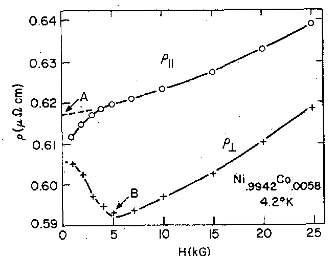
(positive vs. negative polarity of AMR/PHE ) Even though the positive polarity is more common, some materials have the negative polarity of AMR/PHE. All nanomagnets, which I have measured so far, have only the positive polarity of the AMR/PHE. The classical review paper on AMR (T.R. Mcguire and R.I. Potter, IEEE Trans. Magn. (1975)) reports mostly the positive polarity, but still there are materials having the negative polarity (See Fig.10). At present, it is not 100 % clear what is the reason for the polarity change, even though there are some reasonable suggestions. Even more, the true origin of the AMR/PHE is not fully understood yet. It is clear that the AMR/PHE has several contributions, which makes this effect very interesting. For example, I measure AMR/PHE for nearly all nanomagnets, which I measure, but yet I have not analyzed the raw data, because both the current- and gate-dependencies of AMR/PHE are complex and unexpected. It is because of the complex origin of the AMR/PHE effect.
(the polarity of AMR/PHE as a feature of the polarity of spin-orbit interaction) The origin of AMR/PHE is due to the asymmetry of the spin-dependent scattering. Due to the spin of localized electrons, the scattering probability of conduction electrons to the left and to the right with respect to the current direction are different. The same spin-dependent scatterings are also the origin of the Anomalous Hall effect (AHE). AHE is independent whether the conduction electrons are spin-polarized or not. A ferromagnetic metal has both groups of the spin-polarized and spin-unpolarized electrons. The spin-dependent scatterings of the spin-polarized electrons also contribute to the AMR/PHE effect. There is a difference in the scattering probability, because the magnetic field of the spin-orbit interaction HSO is different for the electron scattered to the left and to the right. When HSO is along the spin direction of the spin-polarized electrons, the energy of a scattered electron becomes smaller and , therefore, the electron scattering probability becomes larger. In contrast, when HSO is opposite to the spin direction of the spin-polarized electrons, the energy of a scattered electron becomes larger and , therefore, the electron scattering probability becomes smaller (see Fig. 10).
In short, the polarity is determined by whether the electron scattering probability is larger for the scattering to the left than the right or it is larger to the right than to the left. The different polarity of the magnetic field HSO of spin- orbit interaction for the electron movement to the left and to the right makes the scattering probability different. Therefore, the difference of the Hso polarity defines the sign of the AMR/PHE effect.
(the polarity of AMR/PHE vs. electron- or hole- dominated conductivity of a metal) The scattering probability is proportional to the product of the Fermi function and the density of states of the metal at the Fermi level. When the density of states increases for a higher energy, the metal is electron- dominated. When the density of states decreases for a higher energy, the metal is hole- dominated. If the metal is strongly hole- dominated, the change of the density of state can overcome the change due to the Fermi function and, therefore, the scattering probability to state of a higher energy may become larger than the scattering probability to state of a lower energy. As a result, the polarity of the AMR/PHE effect changes. There are several possible contributions to the AMR/PHE effect. The above- described polarity change is only for the contribution shown in Fig. 10.
![]() (quastion 1) PHE voltage looks to be proportional to the first derivative of AMR by angle between current density and magnetization (this looks to be direct evidence from the formulas). (PHE ~ d(AMR)/d(thetaM)) Is there a possibility to show that PHE ~ d(AMR)/d(thetaH)) or PHE ~ d(AMR)/d(H)), where thetaH is the angle between current and field H? In experiments, it often looks like this, even in systems, where magnetization and the field angles are not the same.
(quastion 1) PHE voltage looks to be proportional to the first derivative of AMR by angle between current density and magnetization (this looks to be direct evidence from the formulas). (PHE ~ d(AMR)/d(thetaM)) Is there a possibility to show that PHE ~ d(AMR)/d(thetaH)) or PHE ~ d(AMR)/d(H)), where thetaH is the angle between current and field H? In experiments, it often looks like this, even in systems, where magnetization and the field angles are not the same.
![]() (quastion 2) What is the physical origin of the similarity between the off-diagonal components of the resistivity tensor (PHE components) and to the derivatives of the diagonal ones (AMR components) by thetaM?
(quastion 2) What is the physical origin of the similarity between the off-diagonal components of the resistivity tensor (PHE components) and to the derivatives of the diagonal ones (AMR components) by thetaM?
PHE and AMR are two sides of one single effect, which is often called the PHE/AMR effect.
In the case of the PHE/AMR effect, the magneto- current is neither parallel nor perpendicular to the main current , but its direction is somewhere between. The perpendicular- to wire component of the magneto-current creates a charge accumulation at the wire edges and, therefore, the Hall voltage. This component is responsible for the PHE effect. The parallel- to wire component of the magneto-current flows either parallel or opposite to the main current.At a fixed voltage, the total current flowing through the metallic wire either increases or decreases due to the magneto- current. It is absolutely similar as the resistance of the wire changes due to the magneto- current. As a result, the parallel- to wire component of the magneto-current is responsible for the AMR effect. In the simplest case, the proportionality between PHE and AMP effect is
PHE~ cos(φ)
AHE~sin(φ)
where φ is the angle of the magneto-current with respect to the wire direction.
If one wants to compare specifically the Hall voltage to the change of resistivity, the math is slightly more complex, but it is basically the same as above.
----------
I do not see the reason why the first derivative of AMR should be relevant. The cosine changes to sine, maybe that is why.
-------
The PHE/AMR is the 2nd- order magneto-transport effect. It means it is proportional to vector product of current and (ether H or S or s) and (ether H or S or s) , where H is the external magnetic field, S is the total spin of localized electrons and s is the total spin of the spin-polarized conduction electrons. The magnetization is S+s.
In the simplest cases when magnetization is in-plane or perpendicular- to- plane, H, S and s are parallel and the PHE/AMR is simple. In other cases, they are not and the PHE/AMR becomes very complex, but interesting.
![]()
![]() I am strongly against a fake and "highlight" research
I am strongly against a fake and "highlight" research ![]()
![]()
![]()
![]()
![]()
![]()
I will try to answer your questions as soon as possible