Dr. Vadym Zayets
v.zayets(at)gmail.com
My Research and Inventions
click here to see all content |

Dr. Vadym Zayetsv.zayets(at)gmail.com |
|
 |
more Chapters on this topic:IntroductionTransport Eqs.Spin Proximity/ Spin InjectionSpin DetectionBoltzmann Eqs.Band currentScattering currentMean-free pathCurrent near InterfaceOrdinary Hall effectAnomalous Hall effect, AMR effectSpin-Orbit interactionSpin Hall effectNon-local Spin DetectionLandau -Lifshitz equationExchange interactionsp-d exchange interactionCoercive fieldPerpendicular magnetic anisotropy (PMA)Voltage- controlled magnetism (VCMA effect)All-metal transistorSpin-orbit torque (SO torque)What is a hole?spin polarizationCharge accumulationMgO-based MTJMagneto-opticsSpin vs Orbital momentWhat is the Spin?model comparisonQuestions & AnswersEB nanotechnologyReticle 11
more Chapters on this topic:IntroductionTransport Eqs.Spin Proximity/ Spin InjectionSpin DetectionBoltzmann Eqs.Band currentScattering currentMean-free pathCurrent near InterfaceOrdinary Hall effectAnomalous Hall effect, AMR effectSpin-Orbit interactionSpin Hall effectNon-local Spin DetectionLandau -Lifshitz equationExchange interactionsp-d exchange interactionCoercive fieldPerpendicular magnetic anisotropy (PMA)Voltage- controlled magnetism (VCMA effect)All-metal transistorSpin-orbit torque (SO torque)What is a hole?spin polarizationCharge accumulationMgO-based MTJMagneto-opticsSpin vs Orbital momentWhat is the Spin?model comparisonQuestions & AnswersEB nanotechnologyReticle 11
|
e-Drugs (Electronic drugs ) PMA sensor. Molecular recognition sensor.Abstract:e-drugs (electronic drugs) are devices designed to identify and destroy specific pathogenic (harmful) biological objects, such as viruses and bacteria, without damaging the environment, e.g., human cells, in the process. The key element to the development of e-drugs is the PMA sensor, which identifies pathogenic biological objects by specific footprints, when it touches a sensor detection surface. It then proceeds to give the command to destroy the pathogenic biological objects.The development of the PMA sensor is a joint work with Ivan Turkevich from SSRC Center, AIST, Tsukuba
|
1935 to 1968, 12 new classes of antibiotics are developed
1969 to 2003 , only 2 new classes of antibiotics are developed
(Problem): ![]() Quick adaptation and resistance of bacteria and virus towards a new drug and antibiotics
Quick adaptation and resistance of bacteria and virus towards a new drug and antibiotics
Just a fact: United Nations estimated that drug-resistant infections could begin to kill 10 million people annually by 2050.
e-drug. Introduction. part 1. |
|---|
| YouTube video |
![]() .........
......... ![]()

 The use of modern achievements and fabrication methods of nanotechnology (electronic) for medical and biological applications
 A. It might be possible. As I know, the size on coronavirus is 700 nm. Such size is relatively large and therefore it might be possible to detect some smaller features of the virus in order to recognize it. I am fabricating and testing nanomagnets as small as 30-40 nm in diameter. (See here). A nanomagnet of diameter of 700 nm I consider as a large or moderate size nanomagnet.
A. Yes. See here. More than 100 different sensors have been fabricated and tested. However, as 2020.04 all measurements, which I did, are for detectors, which detection surface is covered by a protection layer (either SiO2 or MgO). All experimental measurements are very encouraging. The sensor can made as small as 30 nm in diameter. The sensor is very sensitive to content of the coverage of its to surface (the detecting surface)
Now I am making a new probe, where I will be able to test detectors without protection layer and therefore I will be able to do some "in- field" testing.
![]() Why the e-drugs and electronic antibiotics are important?
Why the e-drugs and electronic antibiotics are important?
Antibiotics are commonly used as a cure, with the goal of killing pathogenic bacteria. However, after being subjected to the antibiotics, the bacteria can remain unaffected and in the process become resistant to this specific antibiotics. The pathogenic bacteria adapt to the "killing" mechanism of the antibiotics and learn how to survive. Scientists then introduce a new type of antibiotic, which being highly effective at first, will outgrow its usefulness as the bacteria obtain resistance to it. Such cause-effect relationship leads to a vicious cycle, which forces more and more different types of antibiotics to be created, without the wanted result ever being reached. Therefore, there arises a need for a new type of drug with a mechanism to overcome the paradox mentioned above.
At present, there are a few medicine, which are able to destroy a virus.![]()
![]() The basic function of the e-drugs is to identify a pathogenic (harmful) bacteria or viruses and destroy them. It is necessary to note that e-drugs only destroy the intended bacteria and leave other biological objects unharmed. The implications of this is that when they are used in the human body, they do not harm the healthy human cells.
The basic function of the e-drugs is to identify a pathogenic (harmful) bacteria or viruses and destroy them. It is necessary to note that e-drugs only destroy the intended bacteria and leave other biological objects unharmed. The implications of this is that when they are used in the human body, they do not harm the healthy human cells.
(main merit of e-drug): it is practically impossible for the bacteria or virus to adapt to the e-drug and to become resistant to it.
![]() Since e-drugs can use several recognition methods to identify the bacteria or virus (See here) and several methods to destroy them (see here), it is practically impossible for the bacteria or virus to adapt to the e-drug and to become resistant to it.
Since e-drugs can use several recognition methods to identify the bacteria or virus (See here) and several methods to destroy them (see here), it is practically impossible for the bacteria or virus to adapt to the e-drug and to become resistant to it.
There are many similarities between the e-drug and the DDS. The main feature that distinguishes between the two, is that e-drug possesses a recognition function foe a biological object. The e-drug contains the PMA sensor, which is able to recognize a biological object. The purpose of the DDS is to deliver medicine to the intended area in the human body. On the other hand, the purpose of the e-drug is to recognize and destroy the biological object that is harming the human body.
It is important for the size of the e-drug should be as small as possible (see here). For most of its applications, the longest size of the e-drug should not exceed 0.5 mm.
(element 1) ![]() (main element). The object/molecular recognitions sensor
(main element). The object/molecular recognitions sensor
The main and the most important part of the e-drug. When a biological object or a molecule touches the surface of the sensor, the sensor gives a signal of whether the object is recognized or not. The PMA sensor is the most suitable sensor to perform the functions(See here). In the present, there are no other sensors, which can perform a similar recognition function (see here).
(element 2) ![]() The container of the "killer" medicine
The container of the "killer" medicine
A container holding a substance, which destroys the pathogenic (harmful) biological object. The “killer” substance is usually an acid, but the action that the “killer” substance takes depends on the properties of the object that is intended to be destroyed.(See here)
(element 3) ![]() The valve
The valve
(option 1): The valve is connected to the container with the “killer” medicine and is opened for a short amount of time when it receives the recognition signal from the sensor. (See here)
(option 2) electroporation (e.g. see here). This technique involves the delivery of a voltage (current) across the surfaces of cells, which will result in the spontaneous creation of pores in the plasma membranes. When the voltage is removed, the pores will close. When the voltage is applied and the pores open up and the "killer" medicine is released.
(element 4) ![]() The ultrasonic tracker & transmitter
The ultrasonic tracker & transmitter
It transmits a tracking signal which is used to track the current position of the e-drug inside the human body and sends the operation information data. Additionally to an ultrasonic transmitter, an electromagnetic transmitter can be used. This element is not mandatory for the e-drug.
(element 5) ![]() Power supplier
Power supplier
The important requirement for the power supplier of the e-drug is its safety for human body. It should be made out of materials that would be not hazardous for human and should not be rejected by the human body. A capacitor-type battery is preferable. An alkaline battery is less preferable. However, an optimized design of alkaline battery is still possible for use in the e-drug.
(element 6) ![]() "Decision making" electronics
"Decision making" electronics
There are several methods for recognizing molecules and biological objects using different algorithms for decision making. The data processing chips can fulfil this function. It is critical for all data-processing electronics to be of a very small size (see here).
e-drug. Operational principal. |
||||||||
|
||||||||
| When a bacteria touches the detection surface of the sensor, the sensor identifies the type of the bacteria using programed fingerprints. In the case when the bacteria is recognized, a small amount of a "destroying" substance (e.g. acid) is sprayed over the pathogenic object and destroys it. Only pathogenic bacteria is destroyed, but other "healthy" bacteria are not damaged | ||||||||
| The green oval bacteria (E-coil bacteria) touches the sensor surface and is not recognized. As a result, it leaves unharmed the proximity of the e-drug | ||||||||
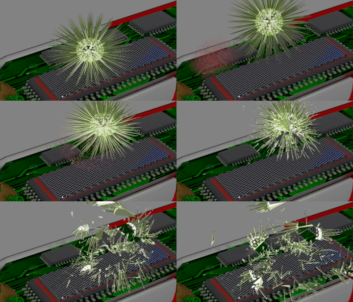
| The yellow spherical bacteria is recognized when it touches the sensor surface. As a result, the "destroying" substance (red powder) is sprayed over the bacteria and destroys it. | ||||||||
| The red powder is only concentrated in the proximity of the e-drug just a short time after it sprayed. It does not damage the green bacteria, because it is far when the red powder is sprayed. | ||||||||
| Click on image to enlarge it. |
(main function) : recognition of a biological object.
(function 2): destruction of the pathogenic object.
(function 3): : tracking the position of the e-drug inside the human body with respect to the organ position
.(function 4): movement and navigation to a specific location in the body (or organ) by an external magnetic field.
Each biological object has specific “fingerprints”, from which it can be identified. The e-drug is programmed to identify these “fingerprints” to distinguish one biological objects from others.
(fingerprint 1:)![]() object sizes (length, width)
object sizes (length, width)
Even though sizes of similar biological objects differ, in general the variation is insignificant (_see SEM image of the E-Coli Bacteria here_). As a result, the object recognition by size is in most cases very effective and should be selected as the first choice.
(fingerprint 2:)![]() object shape (spherical, oval, star-like)
object shape (spherical, oval, star-like)
Biological objects have a huge variety of shapes (See SEM images here). The object recognition by its shape should be used to distinguish different objects of about the same size, but different shape. This recognition method is the first choice for recognition of viruses, because they have very identifiable shapes(See SEM images here).
(fingerprint 3:)![]() object environment (amounts of carbohydrates, amino-acids and other elements in the proximity of the object)
object environment (amounts of carbohydrates, amino-acids and other elements in the proximity of the object)
Any living biological object actively interacts with surrounding biological environment. It constantly injects and absorbs simpler biological objects (sugar, amino-acids, DNA and RNA molecules) from/to the surrounding environment. As a result, the content of surrounding environment are change near the living biological object and it is specific for each living biological object. By checking the environmental change, the type of the biological object can be identified. This recognition method is the first choice for recognition of cells, because many different cells have nearly identical shape and form despite of their substantial internal difference. E.g. a cancer cell consumes substantially larger amount of carbohydrates, amino-acids etc. As a result, their contents are substantially different in proximity of a cancer cell and in proximity a healthy cell. The e-drug (the PMA sensor) can measure the difference and therefore distinguished between cancer and healthy cells.
(fingerprint 4:)![]() object surface (specific structure of the object surface).
object surface (specific structure of the object surface).
Every biological cell is surrounded by a membrane and a cell wall. Most of cells are distinguished by their internal structure. Their external structure is very similar. They have nearly-identical the membrane and the cell wall. However, the structure, features, elements and the shape of the surrounding membrane may be slightly dissimilar between different types of cells. In some cases, the sensor may recognize the type of the cell by touching its membrane.
A cancer cell produces a different amount of a specific type of amino acid from a similar healthy cell. That is due to the fact that cancer cells consume sugar at a higher rate than healthy cells, and they are also “hungry” for amino acids, the building blocks of proteins and other biomolecules (e.g. see here). By measuring the amount of that specific amino acid in the close proximity to the cell, a cancer cell can be distinguished from a healthy cell.
![]() How to destroy a pathogenic (harmful) biological object?
How to destroy a pathogenic (harmful) biological object?
![]()
![]()
![]() In this case, a container with a micro-sized electronic valve is integrated into the e-drug. The container holds a small amount of a "killer" medicine. An acid is the most suitable as the “killer”, but another substance can be used as well. The "killer" medicine is specific for each specific pathogenic (harmful) biological object, which is intended to be destroyed.
In this case, a container with a micro-sized electronic valve is integrated into the e-drug. The container holds a small amount of a "killer" medicine. An acid is the most suitable as the “killer”, but another substance can be used as well. The "killer" medicine is specific for each specific pathogenic (harmful) biological object, which is intended to be destroyed.
![]() Operational principle: After the pathogenic (harmful) biological object is identified, a small amount of the "killer" medicine is released to the direction of the pathogenic (harmful) object, destroying it. The "killer" medicine is quickly dissolved in the surrounding environment and, therefore, does not damage other healthy biological objects.
Operational principle: After the pathogenic (harmful) biological object is identified, a small amount of the "killer" medicine is released to the direction of the pathogenic (harmful) object, destroying it. The "killer" medicine is quickly dissolved in the surrounding environment and, therefore, does not damage other healthy biological objects.
![]() (merits): (1) Simplicity of operation. (2) Nearly all types of the pathogenic (harmful) biological objects can be destroyed.
(merits): (1) Simplicity of operation. (2) Nearly all types of the pathogenic (harmful) biological objects can be destroyed.
![]() (demerits):(1) The "killer" medicine cannot be recharged. (2) Fabrication of a micro-sized electronic valve is technologically challenging. (3) Even though a tiny amount of the killer medicine is released, it can be slightly poisonous to the surrounding environment. (4) This method cannot be used in an environment with a high density of biological objects (cells). When there are many cells in close proximity to the e-drug, the damage to the healthy cells is unavoidable.
(demerits):(1) The "killer" medicine cannot be recharged. (2) Fabrication of a micro-sized electronic valve is technologically challenging. (3) Even though a tiny amount of the killer medicine is released, it can be slightly poisonous to the surrounding environment. (4) This method cannot be used in an environment with a high density of biological objects (cells). When there are many cells in close proximity to the e-drug, the damage to the healthy cells is unavoidable.
|
 |
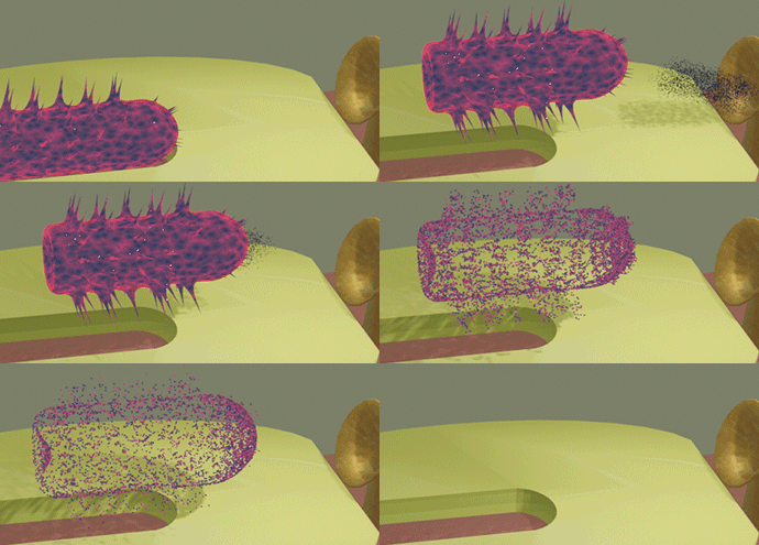 |
| The killer medicine (red or black powder) is sprayed over the pathogenic (harmful) object destroying it. |
| An acid may be used as the killer medicine, but another substance can be used as well |
![]()
![]()
![]() In this case, the pathogenic (harmful) biological object is electrocuted by applying an electrical voltage between its parts
In this case, the pathogenic (harmful) biological object is electrocuted by applying an electrical voltage between its parts
![]() Operational principle: After the pathogenic (harmful) biological object has touched the surface of the sensor and is identified, an electrical voltage is applied between two electrodes, which are close to the sensor. The pathogenic (harmful) biological object is electrocuted.
Operational principle: After the pathogenic (harmful) biological object has touched the surface of the sensor and is identified, an electrical voltage is applied between two electrodes, which are close to the sensor. The pathogenic (harmful) biological object is electrocuted.
![]() (merits): (1) Simplicity of fabrication.
(merits): (1) Simplicity of fabrication.
![]() (demerits): (1) Biological environment is electrolyte and thus is conductive. Therefore, often it is difficult to apply a sufficient voltage to electrocute the pathogenic (harmful) object. (2) In the case when the pathogenic biological cell is not fully destroyed, but only partially damaged, it can become a cancer cell. For the same reason, a DC voltage applied to a human body can cause cancer. (3) The power consumption is high. (4) A substantial conductivity of a biological environment makes it difficult to apply a sufficient destroying voltage.
(demerits): (1) Biological environment is electrolyte and thus is conductive. Therefore, often it is difficult to apply a sufficient voltage to electrocute the pathogenic (harmful) object. (2) In the case when the pathogenic biological cell is not fully destroyed, but only partially damaged, it can become a cancer cell. For the same reason, a DC voltage applied to a human body can cause cancer. (3) The power consumption is high. (4) A substantial conductivity of a biological environment makes it difficult to apply a sufficient destroying voltage.
See conductivity of a biological environment
![]()
![]()
![]() In this case, the pathogenic biological object is destroyed mechanically. It is squashed or pierced through mechanical movements of some parts of the e-drug. This function is implemented by a MEMS (Micro Electro-Mechanical Systems) circuit. Feature of a MEMS circuit is that its parts a MEMS circuit can mechanically move relatively each other under an applying a voltage due the electrostatic force. The electrostatic force can be programmed. When the pathogenic biological object is between the moving path parts a MEMS circuit, its is destroyed under the electrostatic forced
In this case, the pathogenic biological object is destroyed mechanically. It is squashed or pierced through mechanical movements of some parts of the e-drug. This function is implemented by a MEMS (Micro Electro-Mechanical Systems) circuit. Feature of a MEMS circuit is that its parts a MEMS circuit can mechanically move relatively each other under an applying a voltage due the electrostatic force. The electrostatic force can be programmed. When the pathogenic biological object is between the moving path parts a MEMS circuit, its is destroyed under the electrostatic forced
![]() Operational principle: The pathogenic biological object is pierced through with a moving needle. (2) The pathogenic biological object is squashed between two moving plates.
Operational principle: The pathogenic biological object is pierced through with a moving needle. (2) The pathogenic biological object is squashed between two moving plates.
![]() (merits): It is the safest method to destroy a pathogenic biological object .
(merits): It is the safest method to destroy a pathogenic biological object .
![]() (demerits): (1) It is hard (but possible) to fabricate a MEMS circuit of a required micro-size. (2) It consumes a relatively-large amount of power.
(demerits): (1) It is hard (but possible) to fabricate a MEMS circuit of a required micro-size. (2) It consumes a relatively-large amount of power.
![]() Steps of the fabrication technology:
Steps of the fabrication technology:
(step 1) Micro-sized semi spherical pits are etched on top of the film, which is made out of the material of the container, using a photo lithography and wet etching.
(step 2) The pits are filled up with "killer" medicine.
(step 3) The pits filled with "killer" medicine are covered up by a semi elastic film.
(step 4) A metallic electrode of a certain shape is deposited on top of the cover film.
(step 5) Under the applied electrical field there is an electrostatic attraction between electrodes, which causes a mechanical force on the cover film. The mechanical force forms a tiny crevice in the cover film. This micro-sized crevice is opened and closed under the voltage applied to the electrodes releasing or blocking the "killer" medicine.
(step 6) Backside is polished out. A metal electrode is deposited on the backside.
(step 7) Fabricated containers are diced to fit the required micro-sized shape.
Yes. An additional pressure is induced through applying a voltage between the top and backside electrodes.
Through the Electrostatic Force.
Syringe- type e-drug |
||||||
|
||||||
| The e-drug is maintained on top of the syringe needle. Shown size of e-drug is not to scale. The size of e-drug is substantially smaller. The syringe needle with maintained e-drug pricks into blood vessel. A power and killer medicine are supplied to the e-drug through the needle. When the cure procedure is finished, the needle with fixed e-drug is safely removed from the body. | ||||||
| Spreading of bacteria in blood system: In the case when an infection bacteria or virus contaminates the human blood system, it quickly spread over whole human body (within a few hours). | ||||||
| Cure procedure of e-drug: When e- drug is inside the blood vessel, it destroys the pathogenic infection. Because of fast blood circulation, the cure procedure can be done relatively quickly (in a few hours). However, it requires a large amount of the killer medicine and power, which can be provided only in the case syringe- type e-drug. | ||||||
| Main Merit of a syringe- type e-drug: it can destroy a large number of pathogenic objects, because it has a continuous and unlimited supply of the killer medicine and electrical power | ||||||
| Click on image to enlarge it. |


 syringe- type e-drug
 (Merits): The following are not required for this design: integration of a power source, a container with a killer medicine and position tracking circuits.
(The usage): In the case of large quantity of pathogenic biological objects needed to be destroyed.
![]() Which type of e-drug is better: the mobile type or syringe type?
Which type of e-drug is better: the mobile type or syringe type?
(Use of the mobile type): The mobile type of the e-drug is beneficial when the e-drug needs to reach a remote place in the human body (e.g. brain) and needs to destroy only a few pathogenic biological objects.
(Use of the syringe type): (1) a substantial amount of killer medicine and power are required; (2) the place to cure is easy to reach by a syringe needle;
![]() Is the e-drug dangerous for the human body?
Is the e-drug dangerous for the human body?

![]() (possible hazard source 1):Malfunction and loss of the e-drug inside of the human body.
(possible hazard source 1):Malfunction and loss of the e-drug inside of the human body.
![]()
 The e-drug is made from materials, which are safe for the human body. The electronic circuits are made from silicon with aluminium or copper electrodes. The PMA sensors are made from a ferromagnetic metal (cobalt or iron or their alloys) and isolation oxides (SiO2 (glass), MgO). All these materials possess no danger to the subject even if the e-drug would malfunction and get lost inside the human body.
![]() (possible hazard source 2): Contamination during the process of destroying the hazardous biological objects.
(possible hazard source 2): Contamination during the process of destroying the hazardous biological objects.
![]()
 Even though the killer medicine is released in a very small amount, it can still contaminate the human body with a hazardous substance. Similarly, even though the electrical field for the electrocution of pathogenic object is applied locally, it can still have some impairing effects on the human body. It is important to always optimize the destroying method of the e-drug to avoid any possible damage to the human body.
![]() When the e-drug is inside of the human body, is it attacked by the human immune system?
When the e-drug is inside of the human body, is it attacked by the human immune system?
All of the materials, from which the e-drug is made, are safe for the human body and should not trigger any protection mechanisms from the human immune system.
The size is the matter |
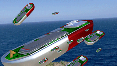 |
| The range of applications of the e-drug strongly depends on their size |
The e-drugs should be as smaller as possible!!! |
| Click on image to enlarge it. |
![]()
![]() The reduction in size is critically important for the e-drug. The range of possible applications of the e-drugs increases substantially as the sizes of the e-drug is decreased.
The reduction in size is critically important for the e-drug. The range of possible applications of the e-drugs increases substantially as the sizes of the e-drug is decreased.
(large size)![]() 1 millimeter-10 millimeter
1 millimeter-10 millimeter
Application of the e-drug is very limited. Mainly, the application of the large-sized e-drugs is limited to the gastrointestinal tract (digestive tract, digestional tract, GI tract, GIT, gut, or alimentary canal)
(target) ![]() drug delivery
drug delivery
(moderate size) 80 micrometers-800 micrometers
Application range of the e-drug is wider, but still limited to the gastrointestinal tract, the respiratory tract, nasopharyngeal tract, etc. The moderate-sized e-drug can be navigated to the body cavities, tubes, ducts and all parts, which are in direct contact with environment outside of human body.
(target) ![]() pathogenic bacteria
pathogenic bacteria
A pathogenic bacteria enters the human body from outside environment (air, food, water etc.) through the channels, which are opened to outside environment. Therefore, the e-drug can be navigated through the exact path, which the targeted pathogenic bacteria entered the human body.
(small size)![]() 5 micrometers-80 micrometers
5 micrometers-80 micrometers
The e-drug is able to reach the most remote and hidden parts of the human body
(target) ![]() cancer cells, virus
cancer cells, virus
![]()
![]()
![]() The reduction of the size of e-drug below 100 micrometers is a key requirement for the most of applications of the e-drug.
The reduction of the size of e-drug below 100 micrometers is a key requirement for the most of applications of the e-drug.![]()
![]()
![]()
PMA sensor ![]()
![]() downscaling feasibility: high
downscaling feasibility: high
A PMA sensor can be made as small as 20 nm x 20 nm. The structure, materials and fabrication technology of the PMA sensor is near identical to that of the Magnetic Random Access Memory (MRAM). In the present, a 40-nm-nod technology is very established and can be used for the e-drug. Even further downscaling is possible for the PMA sensor (See here).
Electronic circuits ![]()
![]() downscaling feasibility: high
downscaling feasibility: high
Required recognition and data-processing functions are not complicated and can be done using simple electronic circuits. The area of a Si transistor in an integrated circuit (IC) is very small (a few hundred square nanometers). Therefore, the electronic circuits can be sufficiently small and fit in the required size limits. The 3D integration of an electronic circuit (See here) is very effective for this purpose.
Power source (battery) ![]()
![]() downscaling feasibility: high
downscaling feasibility: high
For safety reasons (see here), the use of a power supplier of a capacitor-type is preferable. Even though an alkaline battery is less preferable, a biologically-safe design of the alkaline battery may be a possible option for the power source. In the case of the use of a high-quality capacitor oxide and a 3D integration of a stock of capacitors, the capacitor-type is able to provide sufficient power for its small volume. It should be noted, that an ability to recharge inductively (See here) is an important requirement for a power source of the e-drug.
container of "killer" medicine ![]()
![]() downscaling feasibility: low
downscaling feasibility: low
The amount of the "killer" medicine in one e-drug is determined by the volume of its container. This condition strongly limits the possible downscaling of the container. Additionally, it is technologically difficult to downscale the controlling electronic valve.
MEMS circuit ![]()
![]() downscaling feasibility: moderate
downscaling feasibility: moderate
Downscaling of a different MEMS circuit is also technologically difficult. However, each year there is a substantial advance in this research topic.
Ultrasonic circuit ![]()
![]() downscaling feasibility: moderate
downscaling feasibility: moderate
The main application of the ultrasonic circuit is in the high-precision active position tracking (See here). The main difficulty for for a micro-sized ultrasonic circuit is to micro-sized "ultrasonic speakers" (ultrasonic antenna). The downscaling is difficult, because it requires the fabrication of micro-sized mechanically-moved parts of the sonic antenna. The usage of a MEMS circuit as an ultrasonic antenna is an option to reduce the size of the ultrasonic circuit.
antenna for emission of ultrasonic wave and microwave ![]()
![]() downscaling feasibility: moderate
downscaling feasibility: moderate
The optimum size of an antenna for the emission of a wave is around the wavelength. The optimum wavelength, at which the wave penetration depth is sufficient, is 0.2-1 mm for an ultrasonic wave and 4-20 mm for a microwave (see here). The unavoidable reduction in the antenna size for downscaling purposes reduces the efficiency of the emission of an ultrasonic wave and a microwave.
|
||
|
||
| The e-drugs contains a small nanomagnet as a sensor. Therefore. it can move inside a human body by a magnetic field | ||
| The magnetic field decays very quickly. Therefore, a simple a permanent magnet can be used to move the e-drug only when it close to skin. | ||
| Click on image to enlarge it. |
![]()
![]()
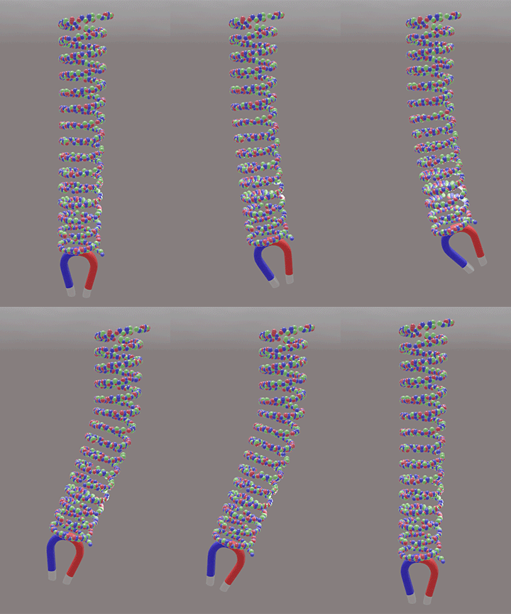
![]() An external magnetic field is used to navigate e-drug inside the human body. There is a small magnet, which is one of the elements of the PMA sensor, inside of the e-drug. The magnet experiences a force in the magnetic field in the direction of the gradient of the magnetic field. The programmable and controlled gradient of the magnetic field drives the e-drug into the desired location.
An external magnetic field is used to navigate e-drug inside the human body. There is a small magnet, which is one of the elements of the PMA sensor, inside of the e-drug. The magnet experiences a force in the magnetic field in the direction of the gradient of the magnetic field. The programmable and controlled gradient of the magnetic field drives the e-drug into the desired location.
![]() The PMA sensor of the e-drug is made of a small nanomagnet, which is attracted by the magnetic field. By programing the intensity and direction of the magnetic field at the current position of the e-drug, the movement direction and the speed of the movement of the e-drug is controlled.
The PMA sensor of the e-drug is made of a small nanomagnet, which is attracted by the magnetic field. By programing the intensity and direction of the magnetic field at the current position of the e-drug, the movement direction and the speed of the movement of the e-drug is controlled.
![]()
![]() The force strength and direction of the force are proportional to the gradient of the magnetic field.
The force strength and direction of the force are proportional to the gradient of the magnetic field.
The magnetic energy Emag of a nanomagnet in a magnetic field H is calculated as
![]()
where M the magnetization of the ferromagnetic metal of the nanomagnet, V is the volume of the nanomagnet. The force Fmag, which acts on the nanomagnet, pushes the nanomagnet toward a smaller magnetic energy. E.g. the magnetic field changes along the x-direction, Fmag can be calculated as

or in the general case, the force Fmag can be calculated as

navigating the e-drug inside a blood vessel in the human brain |
||||
|
||||
| The electronic dug is navigated along a complex path in a blood vessel in the brain. Its current position with respect to vessel is tracked by an active tracking. A pair of orthogonal electro- magnets provides a magnetic field. The direction and value of the gradient of the magnetic field is precisely programmed at the current position of the e-drug. It controls the direction and speed of the movement of the e-drug. The PMA sensor monitors the environment in he vessel. It allows to move through the vessel smoothly without hitting the vessel walls. | ||||
| The precision of the position tracking should beat least 20 um with respect of the vessel position and 50 um with respect to world position. | ||||
| Two pair of a strong magnets are required to set a gradient of the magnetic field at exact position of the e-drug at programmed direction and intensity | ||||
| See Drug delivery to the brain in wikipedia | ||||
| Click on image to enlarge it. |
In fact, a small permanent magnet may produce a larger magnetic field than a large electromagnet. Even more importantly, a small permanent magnet is able to produce a larger gradient of the magnetic field, which is not an absolute value, that being an important characteristic for the e-drug.

 The smaller gap between poles of magnets, the larger the gradient and the absolute value of the magnetic field that a magnet can produce.
A magnetic field of 10 KGauss and gradient of 1 kG/cm can be produced by an electro magnet in the gap of 2-3 cm. A magnetic field of 200-300 Gauss and gradient of 20-30 Gauss/cm can be produced in the gap of 40 cm.
A permanent magnet has a small gap between its poles. As a result, it produces a large field. Due to its specific shape, the gradient of the magnetic field is large near the permanent magnet. A permanent magnet is a perfect option for navigation of the e-drug. However, the magnetic field decays rapidly at a longer distance from the magnet. The field of the permanent magnet cannot be electronically reprogrammed.
Yes, but it strongly depends on the specifics of the application. Two important conditions have to be satisfied:
(Condition 1): There should be a sufficient gradient of the magnetic field at the position of the e-drug. The required gradient is relatively easy to create when the position is near the skin. It is much more difficult to create when the e-drug is deep inside the body or the brain.
(Condition 2): The volume of the magnet should be sufficiently large in comparison to the whole volume of the e-drug. E.g. the volume of the nanomagnet should be at least 20-30% of the whole volume of the e-drug.
Two pairs is the minimum amount. Designing the electromagnet for the navigation of the e-drug is a challenging engineering task. It is especially difficult when a large gap between the poles of the magnet is required. The size of the gap between the poles has lower bound limited by the size of a human head or a human body.
The navigation of the e-drugs requires a programmable gradient, direction and magnitude of which can be programmed for the current position of the e-drug. To comply with this requirement, a very complex design of the magnet with several poles of different shapes is necessary.
|
|
Yes, but it is still possible to keep the PMA sensor operational in the navigating magnetic field. Usually, the bias magnetic field is substantially larger than the magnetic field used for the navigation. Therefore, there is a distortion from the navigation magnetic field, but still the operation of the PMA sensor is possible.
The samarium cobalt SmCo and neodymium NdFeB magnets are the best permanent magnets. (see more here)
It is the gradient of magnetic field and not its absolute value that is important for the e-drug. Therefore, the effectiveness of the permanent magnet largely depends on the magnet design. Of course, the magnet of a larger magnetic field can produce a larger gradient of the magnetic field. The value of the gradient strongly depends on the form of the magnet.
An electromagnet: 1 Tesla (10 kGauss) in a 10 cm gap.
A superconductive magnet : 7 Teslas (70 kGauss) in a 50 cm gap
The use of a superconductive magnet for drug navigation is very desirable. A special design, which is different from the design of the MRI magnet, should be used. The magnetic nucleus resonance depends on the absolute value of the magnetic field. In contrast, the drug navigation requires a programmable gradient of the magnetic field.
(target) ![]() pathogenic bacteria
pathogenic bacteria
Usually a pathogenic bacteria enters the human body from outside environment (air, food, water etc.) through the channels, which are opened to outside environment. Therefore, the e-drug can be navigated through the exact path, which the targeted pathogenic bacteria entered the human body. Even though the size of e-drug (~100 um) is much larger than size of a bacteria (1-10 um), the e-drug is able break through some possible obstacle when a substantial gradient of magnetic field is applied.
(target) ![]() cancer cells, virus
cancer cells, virus
The e-drug can be injected into a blood vessel and be navigated through it to a required remote point.
(target) ![]() virus
virus
The e-drug can be injected into a blood vessel and be navigated through it to a required place.
The distance between cells in most of the organs is less than 3 nm. The size of the e-drug is substantially larger. In the case when a strong gradient of the magnetic field is applied, the e-drug can break through the densely-packed cells of the organ. In that event, some damage to the cells is possible. However, this damage is substantially smaller than the damage from a syringe needle.
No. Any possible motor or engine consumes too much power. Its structure is too complex and its size cannot be reduced. The use of a nanomagnet and an externally-created programmable gradient of magnetic field might be only one feasible option to navigate the e-drug, because its simplicity and size scalability. The reduction of the size of the e-drug is critically important requirement.
It is possible for the e-drug to be recharged inductively through the skin when it is inside the human body.
The capacity battery of the e-drug is small and the recharging is very desirable.
![]() An inductive (wireless) recharge is very common for wireless devices such as smartphone, wireless irons and so on.
An inductive (wireless) recharge is very common for wireless devices such as smartphone, wireless irons and so on. ![]()
The inductive charging is very common for embedded medical devices and widely used (see wiki page). Major challenge to realize the inductive charging in a small-size e-drug (100 um and smaller)
![]() there are two tracking types: (type 1) passive, when the e-drug only reflects ultrasonic tracking signal; (type 2) active, when the e-drug transmits an ultrasonic tracking signal.
there are two tracking types: (type 1) passive, when the e-drug only reflects ultrasonic tracking signal; (type 2) active, when the e-drug transmits an ultrasonic tracking signal.
![]() there are two tracking method: (method 1) radar method, when the time delay of a tracking pulse is measured; (type 2) Phase-measuring method, when phase delay of the tracking signal is measured.
there are two tracking method: (method 1) radar method, when the time delay of a tracking pulse is measured; (type 2) Phase-measuring method, when phase delay of the tracking signal is measured.
radar/sonic type positioning |
|||||||||||||
| For radar/sonic type of positioning, delay of pulse traveling for the e-drug to the outside detector is measured | |||||||||||||
|
|||||||||||||
|
|||||||||||||
|
|||||||||||||
The conventional radar or sonic type positioning only can use for rough positioning of the e-drug inside the human body. Only an ultrasonic pulse can be used for this purpose. |
|||||||||||||
| The radar or sonic type positioning is used in a submarine sonic radar, in a car radar and so on. |
![]() (tracking type 1) :
(tracking type 1) : ![]()
 passive type
In case of the passive tracking, the e-drug does not transmit any tracking signal. Ultrasonic waves are illuminated from outside of the body. The signal reflected from the e-drug is detected and its position of the e-drug is determined. The method is similar to that used for an ultrasonic medical examination. (see Acoustic microscopy, Medical ultrasound)
![]() Only large-size e-drug can be detected
Only large-size e-drug can be detected
The e-drug should be covered by a high-refractivity material to enhance the sensitivity of the passive tracking (to enhance the reflectivity of the ultrasonic waves)
![]() (tracking type 2):
(tracking type 2):![]()
![]() active type
active type ![]()
n the case of the active tracking, the e-drug transmits a tracking signal. The tracking signal is detected by several detectors outside of the body.
![]() The active tracking is unavoidable for the e-drug when its size is smaller than 0.4 mm.
The active tracking is unavoidable for the e-drug when its size is smaller than 0.4 mm.
The passive tracking is limited by the diffraction effect. When the size of an object is smaller than the wavelength, it does not reflect the waves, thus becoming invisible to them. The active tracking resolves this problem.
The precision of the radar tracking is limited by the wavelength. It cannot be better than 3λ.
The most- precise active phase-measuring tracking is limited by the ability to detect the phase of the tracking signal transmitted from the e-drug. The precision of 0.3 degrees of detection of the phase of the tracking signal is a well established technology. The sensitivity of the phase detection can be further improved if more high-sensitivity well-synchronized detectors are used.
(Reason 1): The distance between the e-drug and the outside detector is in the range 1cm-30 cm. It is too short distance for the radar.
(Reason 2): The required positioning precision is about 5-30 micrometers. It is too accurate for the radar or GPS methods.
The phase-measurement position methods are more suitable for accurate tracking positioning of the e-drug.
In this method, the phase of the tracking signal, which is transmitted by the e-drug, is measured by several outside detectors. Both the ultrasonic wave (λ=0.1-1 mm) and microwave ( λ=5-40 mm) can be used as a tracking signal. The resolution of this method is about λ/100- λ/1000. See Figs 23 and 24
In this tracking method, the time delay of the tracking pulse, which is transmitted or reflected by the e-drug, is measured by an outside detector. Only the ultrasonic pulse (delay time ~200 microseconds see table) can be used as a tracking pulse. A microwave pulse can be used for synchronization. The shortest pulse interval, which can be used for the pulse delay measurement, should be longer than 5λ. The best resolution of the radar method is also about 5λ or 0.7-1.5 mm (See fig 23)
Wavelength and penetration depth of ultrasonic waves |
||||||
|
||||||
Wavelength and penetration depth of microwaves |
||||||
|---|---|---|---|---|---|---|
|
||||||
| Fig24 | ||||||
| Click on image to enlarge it. |
In the case of active tracking both ultrasonic waves and microwaves can be used. The benefits of the ultrasonic wave are a deeper penetration depth and a smaller wavelength. The benefit of the microwave is that the electronic circuits for microwaves are better developed. Simultaneous usage of both ultrasonic and microwave signal is a good option for position tracking.
For the passive tracking, the use of the ultrasonic waves is preferable.
Human body and/or human organs can slightly move during the e-drug navigation. The position of the navigation magnet is fixed. Therefore, a high- precision position tracking is required to be relative to both the magnet position and the organ position!!
Resolution of the conventional equipment for the ultrasonic medical test: The resolution depends on the wavelength of the ultrasonic wave. The choice of the wavelength depends on the purpose and object of the study. Superficial structures such as muscle, tendon, testis, breast, thyroid and parathyroid glands, and the neonatal brain are imaged at a higher frequency (7–18 MHz; λ=220 -85 micrometers; ), which provides better linear (axial) and horizontal (lateral) resolution. Deeper structures such as liver and kidney are imaged at a lower frequency 1–6 MHz (λ=1.5- 0.25 mm;) with lower axial and lateral resolution as a price of deeper tissue penetration. (see Medical ultrasound). Note: the maximum position tracking precision is about the wavelength used.
Higher-frequency ultrasound would result in a greater detail, but it does not penetrate as well as lower frequencies do. The accepted rule of thumb is that you can effectively scan to a depth of about 500 λ into tissue.
Two conditions should be satisfied:
(1) the penetration depth should be sufficiently deep;
(2) wavelength should be as short as possible in order to increase the tracking precision.
Ultrasonic wave : 1MHz- 15 MHz
Microwave: 1 GHz-12 GHz
For the precise position tracking, the phase of the tracking wave is measured. The phase may change from 0 to 360 degrees. Therefore, the precise tracking can measure position within the range of the wavelength with precision of about 0.1-1 degree.
The rough position tracking (the radar type) has no limitation on the measurement range. The measurement precision of the rough tracking cannot be better than 3λ. Therefore, it is about 1 mm. (see Fig.23)
Minimum 3 (X-,Y- and Z- coordinates). Having more detectors is better.
The optimum size of an antenna for the emission of the wave is about a wavelength. The optimum wavelength, at which the wave penetration depth is sufficiently deep, is 0.2-1 mm for an ultrasonic wave and 4-20 mm for a microwave. Unavoidable reduction of the antenna size for downscaling reduces the efficiency of the emission of an ultrasonic wave and a microwave. This problem can be partially solved by improving the sensitivity of the external detectors. In case of the active tracking the downscaling problem is not as severe as in the case of passive tracking. In the case of the passive tracking, the smaller-size e-drug becomes fully invisible. The case of the active tracking is much better: even a smaller-size antenna emits a lot of waves.
Molecular mask. |
 |
| Molecular mask fabricated on top of MTJ- type PMA sensor |
| The opening in mask are matched to size and shape of analyte molecule |
| Click on image to enlarge it. |
![]() The molecular mask has openings, which match the size and the shape of the molecules, which should be detected.
The molecular mask has openings, which match the size and the shape of the molecules, which should be detected.
![]() How is it possible to fabricate a mask having such tiny features? Is it beyond the limits of modern lithography?
How is it possible to fabricate a mask having such tiny features? Is it beyond the limits of modern lithography?
The lithography cannot be used to fabricate the molecule mask. The special fabrication methods have to be used.
PMA sensor. Molecular detection using a mask |
||||
|
||||
| Fig.21 Molecular recognition method using a mask. The molecular mask of a non‐magnetic material is deposited on the top of the ferromagnetic film. The composition of the molecular masks and size of the openings in the mask specifically match the shape, size and chemical nature of the analyte molecules | ||||
| Click on image to enlarge it. |
(Step 1): The non-organic material of the mask is mixed with the biological material, which is intended to be detected (e.g. specific virus, bacteria or molecule).
(Step 2) The mixture is deposited on top of the ferromagnetic metal (on the detection surface) using a spin coater. The rotation speed of the spin coater is sufficiently fast so that one or a few layers of the mask would remain on the ferromagnetic metal.
(Step 3) The sensor is etched in the oxygen plasma. All organic materials are etched out (are removed) by the oxygen plasma, but the non-organic material of the masks remains unaffected. As a result, the biological objects(bacteria, viruses, etc.) etched out (are removed), but the material of the mask remains on the top of the detector and there are openings at places where the biological objects were originally adhered to the sensor surface.
(Step 1): A biological object (a bacteria, a virus or a molecule), which is intended to be detected, is deposited on the top of the detector.
(Step 2): The mask material is deposited on top of the detector by atomic layers. The deposition method is similar to the Atomic Layer Deposition (ALD) method. The material of the mask is deposited only at places where detector is not covered with biological objects. The feature of this deposition method is that there is no mask deposition on the top of the biological object.
(Step 3): The sensor is etched in the oxygen plasma. The biological objects are etched out (are removed). The material of the mask remains on the top of the detector. there are openings at places where the biological objects were originally adhered to the sensor surface.
![]() How does the mask help to recognize a molecule?
How does the mask help to recognize a molecule?
Molecular mask. Operation method. |
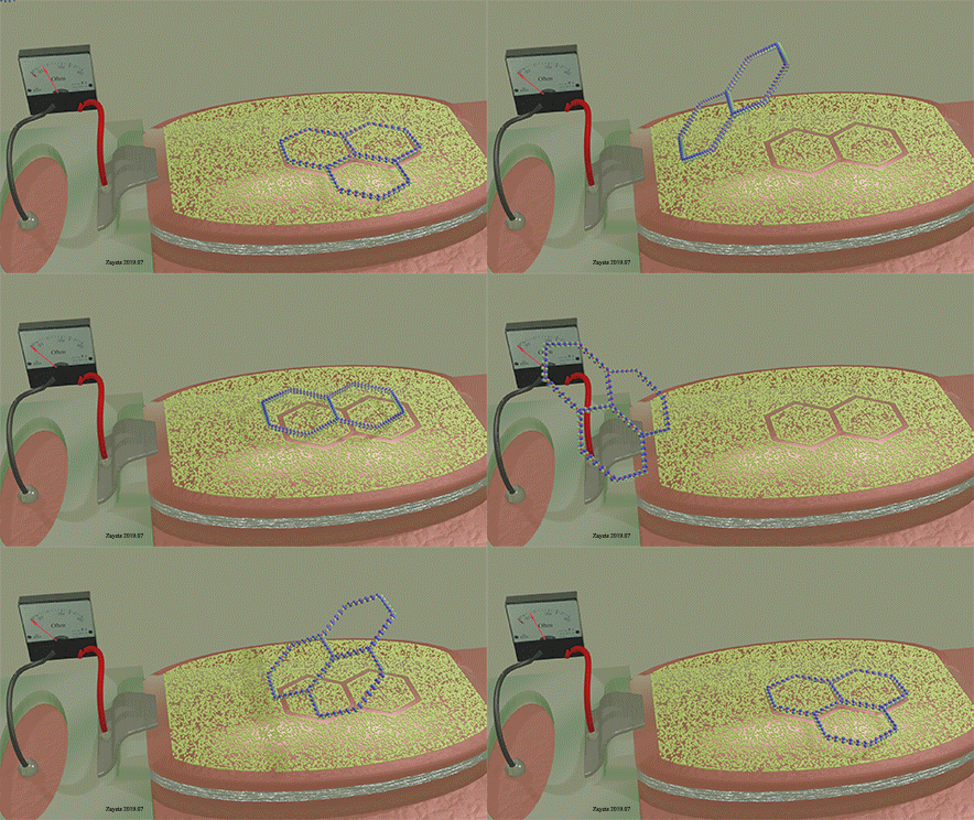 |
| Detection principle of a molecule using a molecular mask |
|---|
| The two-ring molecule perfectly matches the mask opening. As a result, it can perfectly fit into the opening and touch the surface of the detector over full area of the opening. When it does, The detection signal is largest. |
| A similar molecule (three-ring molecule), which is slightly mismatched to the shape of the opening, only partially fits to the opining. As a result, it is unable to cover the whole open area of the detector. At any position of three-ring molecule on the mask, the detection signal is weak. |
| A voltage is applied between electrodes of MTJ (not shown) |
| Click on image to enlarge it. |
Figure 20 and figure 21 show a ferromagnetic film with a molecular mask on top of it. The mask is designed in such a way that it allows only specific molecules to approach the interface of the film. Only molecules of a specific size, shape and chemical composition can pass through the openings of the molecular mask and can be detected by the disclosed sensor. Figure 21 (left) shows the case where a molecule does not fit into the opening of the mask. Therefore, it cannot approach the interface of the ferromagnetic metal. The orbitals on the surface of the ferromagnetic metals are unaffected by the molecule. As a result, the molecule is not detected by the sensor. Figure 21 (right) shows the case where a molecule matches the opening of the mask. Therefore, it can fit into the opening and can approach the interface of the ferromagnetic metal. The orbitals on the surface of the ferromagnetic metal are deformed. As a result, the molecule is detected by the sensor. By designing the shape of the openings and the material of the mask, only a specific type of molecules can reach the surface of the ferromagnetic metal and be detected. Therefore, the sensor is able to recognize this specific type of molecule.
A two-ring molecule, which form and size match the mask opening, gives a large detection signal. A three-ring molecule of an unmatched shape gives a weak detection signal.
![]() The mask has openings, which match the size and shape of the biological object (e.g. virus, bacteria), which are intended to be detected.
The mask has openings, which match the size and shape of the biological object (e.g. virus, bacteria), which are intended to be detected.
Ordinary mask. Operation method. |
||||||||||
|
||||||||||
| Detection principle of a virus or bacteria using an ordinary mask | ||||||||||
|---|---|---|---|---|---|---|---|---|---|---|
| The size and shape of the mask opening is matched to size and shape of the rabies bacteria. As a result, it can perfectly fit into the opening and touch the surface of the detector over full area of the opening. When it does it, the detection signal is largest and the rabies bacteria | ||||||||||
| When a bacteria of a smaller size touches the detector surface through the mask opening, it covers only a small area of the opening. As a result, the detection signal is largest and the smaller bacteria leaves unharmed. | ||||||||||
| When a bacteria of a larger size touches the detector surface through the mask opening, its shape does not fit to the opening and it remains mainly under detector surface without touching the detector surface. As a result, the detection signal is small and the larger bacteria leaves unharmed. | ||||||||||
A voltage is applied between electrodes of MTJ (not shown) |
||||||||||
| Click on image to enlarge it. |
![]() Is it possible to use lithography to fabricate the mask?
Is it possible to use lithography to fabricate the mask?
Yes. A standard nanofabrication process, which includes lithography, can be used for the fabrication of the mask.
(Step 1): The pattern of the electron- of photo- resist having the shape and size of analyte biological object is fabricated on the top of the detector using an Electron lithography or UV lithography.
(Step 2): Mask material is deposited on the top of the detector, which is covered by the patterned resist.
(Step 3): The resist is removed by the lift-off process, creating openings in the mask.
(Step 1): The non-organic material of the mask is mixed with the biological material, which is intended to be detected (e.g. specific virus, bacteria or molecule).
(Step 2) The mixture is deposited on top of the ferromagnetic metal (on the detection surface) using a spin coater. The rotation speed of the spin coater is sufficiently fast so that one or a few layers of the mask would remain on the ferromagnetic metal.
(Step 3) The sensor is etched in the oxygen plasma. All organic materials are etched out (are removed) by the oxygen plasma, but the non-organic material of the masks remains unaffected. As a result, the biological objects(bacteria, viruses, etc.) etched out (are removed), but the material of the mask remains on the top of the detector and there are openings at places where the biological objects were originally adhered to the sensor surface.
(Step 1): A biological object (a bacteria, a virus or a molecule), which is intended to be detected, is deposited on the top of the detector.
(Step 2): The mask material is deposited on top of the detector by atomic layers. The deposition method is similar to the Atomic Layer Deposition (ALD) method. The material of the mask is deposited only at places where detector is not covered with biological objects. The feature of this deposition method is that there is no mask deposition on the top of the biological object.
(Step 3): The sensor is etched in the oxygen plasma. The biological objects are etched out (are removed). The material of the mask remains on the top of the detector. there are openings at places where the biological objects were originally adhered to the sensor surface.
Only the biological object (rabies virus), which form and size match the mask opening, can give a large signal. The smaller or larger biological objects give a weaker signal. The destroying event is only triggered by a large signal.
 Area of sensors
Area of detectors |
||||||
|
||||||
| From 2D image a complex biological object, the object can be recognized. Also, two nearly identical objects can be distinguished from each other. | ||||||
| Click on image to enlarge it. |
![]() The size of a single PMA detector may be as small as 20 nm. There are many large biological objects with size as large as 10 micrometers. Using an array of a tiny PMA detector, the features (e.g. the shape of the object, the temporary deformation of the object shape and features of the object surface) of such large objects can be studied in great detail.
The size of a single PMA detector may be as small as 20 nm. There are many large biological objects with size as large as 10 micrometers. Using an array of a tiny PMA detector, the features (e.g. the shape of the object, the temporary deformation of the object shape and features of the object surface) of such large objects can be studied in great detail.
The area of the PMA can give real-time image of the surface of a biological object, to which it touches ![]() ( Eye to nanoworld)
( Eye to nanoworld)
PMJ sensor as a real-time camera in nano world |
||||||||
|
||||||||
| Click on image to enlarge it. |
 Recognition of interaction
![]() Each material interacts differently with the detection surface of the PMA detector. As a result, different materials change the PMA energy, and therefore the strength of the detection signal is different from material to material. Monitoring the strength of the detected signal can lead to certain additional features of the biological object to be intensified, which may help recognize the object.
Each material interacts differently with the detection surface of the PMA detector. As a result, different materials change the PMA energy, and therefore the strength of the detection signal is different from material to material. Monitoring the strength of the detected signal can lead to certain additional features of the biological object to be intensified, which may help recognize the object.
PMA sensor. Detection principle |
||||
|
||||
| Fig.30. The cross-section of a nanomagnet is shown as an array of its electronic orbitals. The analyte molecule is detected by increase of HSO and the increase of EPMA | ||||
| Click on image to enlarge it. |
The molecular recognition sensor detects a molecule or a biological object by measuring the change of perpendicular magnetic anisotropy (PMA) of a single-domain ferromagnetic metal (nanomagnet). The PMA is changed when the analyte molecule touches the ferromagnetic metal. When the molecule is close to surface of the ferromagnetic metal, the electron orbitals of the molecule and the surface atoms of the ferromagnetic metal interact with each other. As a result, the orbitals of the surface atoms of the ferromagnetic metal are deformed toward the analyte molecule and the PMA energy is changed. From the measurement of the PMA energy, the proximity, type and concentration of the analyte molecules are determined.
The detection method of the PMA sensor is based on the fact that the PMA energy of a ferromagnetic metal depends on the orbital deformation of the surface atoms, which is caused by their interaction with an analyte molecule. The orbital deformation changes the strength of the spin-orbit (SO) interaction for the electrons of the surface atoms of the ferromagnetic metal. The detailed explanation, why the change of the SO interaction causes the change of the PMA of the ferromagnetic metal, can be found here (See PMA , see Spin-orbit interaction) .
Figure 30 explains the detection principle of the PMA sensor. When the analyte molecule is far from the interface of the ferromagnetic film, the deformation of interface orbitals is small, magnetic field of spin-orbit interaction (HSO) is small and the interface PMA is small (Fig. 30 left). When the molecule approaches the interface, the electron orbitals on the surface of the ferromagnetic metal deform toward the analyte molecule (or in the opposite direction). The orbital deformation leads to an increase of the HSO and consequently to the increase of the PMA energy EPMA. By measuring the change of the EPMA, the approach of the analyte molecule can be detected and the type of the analyte molecule can be recognized. Additionally, the concentration of the analyte molecules can be measured. (See more details in the spin-orbit interaction and PMA)
PMA sensor. Detection principle |
||||
|
||||
| The type of the orbital deformation depends of material of the sensor and type of the chemicals of analyte molecule. | ||||
| Click on image to enlarge it. |
It does not matter whether orbital is elongated or squeezed. Both deformations induce the same polarity of the change of HSO. A breaking the spacial symmetry is important, but not the polarity of the breaking. The most effective enhancement of HSO is when the center of electron orbital is shift of the position of the nucleus. (See more details in the spin-orbit interaction)
Figure 35 shows the Hall‐probe sensor, which consist of a Fe nanomagnet (grey color) on the top of a Ta nanowire (yellow color) with an SiO2 isolation layer (green color). The nanomagnet is made of a ferromagnetic metal (Fe) . The nanowire and the Hall probe are made of a non‐magnetic metal (Ta). The equilibrium magnetization of the nanomagnet is perpendicular‐to‐plane. An external magnetic field H is applied along the wire. Under the magnetic field, the magnetization of the nanomagnet inclines towards the in‐plane direction. The ball with arrow shows the magnetization direction of the nanomagnet. A bias current is passed along the nanowire. Two Hall probes are contacting the nanowire to detect the Hall voltage. The Hall voltage is linearly proportional to the perpendicular‐to‐plane component of the magnetization. The proximity, type and concentration of the analyte molecules are detected by measuring the Hall voltage.
When the analyte molecule is far from surface of the nanomagnet. The PMA energy is small. The magnetization of the nanomagnet is inclined more to the in-plane direction. As a result, the Hall voltage is small.
When the analyte molecule is near the surface of the nanomagnet. The PMA energy becomes larger. The magnetization of the nanomagnet is inclined more to the perpendicular-to-plane direction and the Hall voltage increases. As a result, the proximity, type and concentration of the analyte molecules are detected.
PMJ sensor. MTJ setup |
||
|
||
| Molecular recognition sensor based on the magnetic tunnel junction (MTJ) | ||
| A voltage is applied between electrodes of MTJ (not shown) | ||
| Click on image to enlarge it. |
![]() MTJ -type is the most-important type, which is suitable in-field sensing
MTJ -type is the most-important type, which is suitable in-field sensing
It is suitable for testing inside human body.
![]() The molecular recognition sensor based on the magnetic tunnel junction (MTJ) consists of:
The molecular recognition sensor based on the magnetic tunnel junction (MTJ) consists of:
(1) a thicker “pin” electrode made of a ferromagnetic metal. Its equilibrium magnetization is in‐plane,
(2) a thinner “free” electrode made of a ferromagnetic metal. Its equilibrium magnetization is perpendicular‐to‐plane
(3) a thin non‐conductive layer between the “pin” and the “free” layers. The “pin” and the “free” layers are made of ferromagnetic metals.
A bias voltage is applied between the “pin” and the “free” layers and a tunneling current flows between the layers.
![]() An external magnetic field Hext is applied in the in-plane direction. Due to the Hext the magnetization of the "free" layer inclines towards the in-plane direction. The inclination angle depends on the . At the same Hext, the magnetization of "free" layer Mfree inclines more towards the in-plane direction, when EPMA is smaller. It inclines less towards the in-plane direction, when EPMA is larger
An external magnetic field Hext is applied in the in-plane direction. Due to the Hext the magnetization of the "free" layer inclines towards the in-plane direction. The inclination angle depends on the . At the same Hext, the magnetization of "free" layer Mfree inclines more towards the in-plane direction, when EPMA is smaller. It inclines less towards the in-plane direction, when EPMA is larger![]()

Figure 35 explains the operation principle of the PMJ sensor of the MTJ- type. The proximity of an analyte molecule is detected by monitoring the tunneling current. The tunneling current depends on the angle a between the magnetizations of the “pin” and the “free” layers. The tunneling current is largest when the magnetizations of the “free” and the “pin” layers are in the same direction. The tunneling current is smallest, when the magnetization of the “free” and the “pin” layers are in opposite directions. An external magnetic field Hext is applied in the in‐plane direction. The magnetization of the “pin” layer (Mpin) remains in the in-plane direction while the magnetization of the “free” layer (Mfree) inclines towards Hext. The inclination angle of the Mfree depends on the PMA energy of the “free” layer and strength of Hext. In the case when there are no analyte molecules in the proximity of the “free” layer, the PMA energy EPMA of the “free” layer is small. The Mfree inclines more to Hext and Mpin direction and the tunneling current is large. When the analyte molecules touch the surface of the “free” layer, the PMA energy of the “free” layer becomes larger and the Mfree inclines more towards perpendicular-to-plane direction. The angle between Mfree and Mpin direction becomes larger. As a result, the tunneling current becomes smaller.
MTJ- type PMA sensor. Detection principle |
||||
|
||||
Itunnel,a> Itunnel,b |
||||
|---|---|---|---|---|
Fig. 35. Detection principle of an analyte molecule by the MTJ. |
||||
| Click on image to enlarge it. |
The proximity of an analyte molecule is detected by monitoring the tunneling current. The tunneling current depends on the angle a between the magnetizations of the “pin” and the “free” layers. The tunneling current is largest when the magnetizations of the “free” and the “pin” layers are in the same direction. The tunneling current is smallest, when the magnetization of the “free” and the “pin” layers are in opposite directions.
An external magnetic field Hext is applied in the in‐plane direction. The magnetization of the “pin” layer (Mpin) remains in the in-plane direction while the magnetization of the “free” layer (Mfree) inclines towards Hext. The inclination angle of the Mfree depends on the PMA energy of the “free” layer and strength of Hext.
In the case when there are no analyte molecules in the proximity of the “free” layer, the PMA energy EPMA of the “free” layer is small. The Mfree inclines more to Hext and Mpin direction and the tunneling current is large. When the analyte molecules touch the surface of the “free” layer, the PMA energy of the “free” layer becomes larger and the Mfree inclines more towards perpendicular-to-plane direction. The angle between Mfree and Mpin direction becomes larger. As a result, the tunneling current becomes smaller.
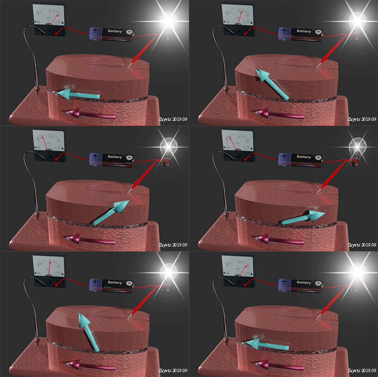
How does a magnetic tunnel junction (MTJ) work? |
||
 |
||
| MTJ consists of two layers of ferromagnetic metal and a thin non-conductive isolator between them. Only a tunneling current flows between electrodes. The magnetization of the bottom layer (red arrow) is in-plain. This layer is called a "pin" layer. The magnetization of the top layer (blue arrow) may change it direction under external influence (e.g. an external magnetic field). This layer is called a "free" layer. | ||
|
||
|---|---|---|
| The resistance is the smallest, when magnetization directions are parallel. | ||
| The resistance is the largest, when magnetization directions are opposite each other. | ||
| Click on image to enlarge it. |
The resistivity of MTJ depends on the mutual magnetization directions of its "free" and "pin" layers. The resistance is the smallest, when magnetization direction of the "free" layer is parallel to the magnetization of "pin" layer. The resistance is the largest, when magnetization directions are opposite each other. The resistance is intermediate, when magnetization direction of the "free" layer is perpendicular to interface.
About 100 % or 2 times for the FeCoB/MgO/FeCoB MTJ.
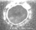
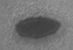
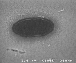
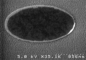
The darker area at center is top surface of nanomagnet
The brighter surrounding is SiO2 isolation layer. The SiO2 layer slightly overlaps the edge of the nanomagnet
 |
 |
 |
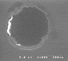 |
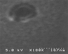
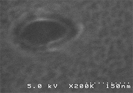
| 60 nm x 120 nm | 70 nm x 140 nm | 90 nm x 200 nm | 700 nm x700 nm |
 |
 |
 |
| 240 nm x570 nm | 1100 nm x1900 nm | 1100 nm x1900 nm |
Cell of Spin-photon memory |
||
|
||
(left) Top view. two Fe nanomagnet contacts on top of p-i-n GaAs photodetector. Nanomagnet diameter: 100 nm, Gap 70 nm (right) Cross-section. (See here for more details) |
![]() Note: magneto resistance of the fabricated MTJ is ~100 %.
Note: magneto resistance of the fabricated MTJ is ~100 %.
No, MR ratio remains the same to be about 100%
No, the tendency is opposite. The sensitivity and the resolution increase.
The MTJ- type PMA sensor is able a biological object when it covers about 5 % of its detection surface. The smaller the detection area of the sensor becomes, the smaller biological object can be detected by the sensor.
Yes. It is because the Hall voltage decreases when the sizes of the nanomagnet decrease
Magnetic tunnel junction (MTJ) |
||
|
||
| (left) reading principle of MTJ (right) top SEM image of fabricated nano -sized MTJ. More details are above |
In the present fabrication technology of the magnetic random access memory (MRAM), the diameter of the MTJ is 20 nm. I, myself, have fabricated a MTJ of diameter as small as 40-50 nm.
No, the technologies are similar, but the fabrication technology of the PMA sensor is more complex. Main difference is that in the case of PMA sensor the top electrode should not cover whole area of the nanomagnet. The structure and materials of the free electrode is very specific for the PMA sensor.
The size of the nanomagnet in the proposed sensor can be fabricated as a small as 20x20 nm2. Nanomagnets of this size are currently used in magnetic random-access memory (MRAM). The integration of MRAM into a Si‐chip is a well‐established commercial technology. For example, a similar technology is used for the fabrication of an embedded MRAM. Therefore, the disclosed sensor is compatible with the CMOS technology and can be fabricated on a Si chip by using currently available MRAM technology. Since the sensor does not have any large bulk components, it can be integrated into a micro-devices, such as electronic medicines, for example electronic antibiotics providing drug release at the point of bacteria detection.
It is possible to detect the change of the PMA, when only 0.5% of interface orbitals of the nanomagnet are deformed. Since the nanomagnet can be fabricated as small as 20x20 nm2, a molecule with an effective area as small as 1x1 nm2 can be detected.
At present, only the PMA sensor is suitable as a sensor for e-drugs |
 |
| All other presently known sensor are not suitable for the e-drug |
| Click on image to enlarge it. |
The reason of the high selectivity of the disclosed sensor is due to its high sensitivity to the interface orbitals deformation that depends on structure and composition of the analyte molecules. As a result, two slightly different molecules can be distinguished. Furthermore, the specificity of the sensor can be enhanced by using molecular masks and transduction ligands that allow interaction with only specific molecules.
The PMA is essentially a surface phenomenon that is based on the deformation of electronic orbitals in only one monolayer at the surface, which in turn results in extraordinary sensitivity of the disclosed sensor.
The response time of the PMA sensor is about 1 ns. Physical limit of the response speed is the frequency of the ferromagnetic resonance (FMR), which is for common ferromagnetic metal is about of a few GHz. Since the time interval of the touching of a biological object to the surface of the sensor, the fast operational speed of the PMA sensor is its great advantage.
 Comparison with other designs of a biological sensor
sensor 1.tag-type  Sensors utilizing fluorescent particles (fluorescent markers or fluorescent tags)
molecule with a fluorescent tag |
||
|
||
| A nano particle, which contains a fluorescent material (e.g. phosphorous) , is attached to the bio molecule. When the molecule is illuminated by ultra violet light, it emit fluorescent light. The fluorescent light is watched in an optical microscope and the position of the molecule can be identified. For example, it can be distinguished whether the molecule is inside the cell nucleus or outside or in which particular cell the tagged molecule is. | ||
| The resolution of molecular position identification is about 0.5-1 micrometer. Two tagged molecules can be distinguished from each other, when the distance between them is about 3-5 micrometers. | ||
| Click on image to enlarge it. |
Main idea: the detection of light from a fluorescent marker. As a result, the position of the molecule can be traced.
![]() Operational principle:
Operational principle:
Step 1: A fluorescent nano-particle (a fluorescent tag or a fluorescent marker) is bonded to a biological molecule.
Step 2: Fluorescence from the particle is observed in an optical microscope
![]() Related Patents:
Related Patents:
US8043802B2 (2002). Title: Fluorescence based biosensor
US5701012A (1996). Fluorescent biological particle detection system
![]() Demerits:
Demerits:
(1) Only biological -molecules, which are marked by a fluorescent tag, can be detected
(2) The resolution is limited by the optical diffraction limit. Two biological objects at distance shorter than 0.5-1 micrometer cannot be distinguished from each other.
Theoretically it is possible by measuring the the intensity of fluorescent light. Practically, it is very difficult and requires a difficult and complex calibration. However, the measurement of the change of the number of the molecules with the a fluorescent tag is easier. For example, the time evolution of the number of the tagged molecule can be measured.
sensor 2.tag-type ![]() Sensors utilizing magnetic nanoparticles as magnetic markers or magnetic tags
Sensors utilizing magnetic nanoparticles as magnetic markers or magnetic tags![]()
bio molecule with a magnetic tag |
 |
| A nano particle, which contains a ferromagnetic material(e.g. iron or cobalt) , is attached to the bio molecule. The size of nano particle is bout 20x20x20 nanometers. Due to the small size, the magnetization of the particle is the same direction ( single-domain state). For this reason, the nano particle is called nanomagnet. |
| merit 1: The tag molecule can be moved inside cell or human body by an external magnetic field (See here) |
| merit 2: the molecule can be identified by measuring the magnetic field from nanomagnet by a magnetic field detector |
| Click on image to enlarge it. |
Main idea: (idea 1) moving the molecule with magnetic marker by external magnetic field (see here); (idea 2) detection of magnetic field of a magnetic marker by a detector of magnetic field (e.g. TMR detector)
![]() Operational principle:
Operational principle:
Step 1: A magnetic nano-particle (a magnetic tag or a magnetic marker) is bonded to a biological molecule.
Step 2: A material, which can capture the biological molecule, is deposited on the surface of a magnetic probe. The magnetic probe uses the magneto-resistance effect.
Step 3: When the biological molecule is captured, the magnetic nano particle induces a magnetic field, which is detected by the magnetic probe.
![]() Related Patents:
Related Patents:
US5981297A (1997). Biosensor using magnetically-detected label. Claim: First usage of magnetic markers for bio -molecule
WO2012068139A1 (2012). GMR sensor. Claim: GMR sensor
JP6043396B2 (2013). Magnetic nanoparticles, magnetic detector arrays, and methods for their use in the detection of biological molecules. Claim: Molecule influence the exchange coupling between two ferromagnetic films.
US20170097337A1 (2017). Method for detecting small molecule analytes using magnetoresistance sensors. Claim: Fabricated and tested sensor.
EP1469311A4. Biosensor, magnetic molecule measurement method, and measurement object measuring method. Claim: Use the semiconductor Hall sensor as a magnetic detector.
![]() Demerits:
Demerits:
(1) Only bio-molecules, which are marked by a magnetic tag, can be detected
(2) Difficulties to detect a very small change of magnetic field, because the magnetic field of the magnetic nano particle is very small. Additionally, the direction of the magnetic field may be different depending on the position, where the bio-molecule is captured by the sensor
(3) Problem of magnetic noise of environment
(4) Difficulties of detection of a single molecule
![]() Main purpose:
Main purpose:
To measure the number of molecules with a magnetic tag.
The number of molecules with a magnetic tag is measured from the total magnetic field all tagged molecules induced together. To obtain the current number of the tagged molecules, the current value of magnetic field measured by a magnetic sensor is divided to the value of the magnetic field induced by one tagged molecule. The detection surface of the sensor of magnetic field is covered by an adhesion material (antibody material) and the magnetic field only from adhered molecules is detected.
Theoretically it is possible, but practically it is impossible to measure accurately, reliably and repeatedly the number of tagged molecules using the method of magnetic tag. It because the detected magnetic field induced by one tagged molecule changes significantly with a very slight variation of adhesion parameters or nanomagnet properties. The detected magnetic field depends on:
(1) either nanomagnet is closer to center or edge of detector;
(2) adhesion distance of nanomagnet from detector;
(3) shape and size of nanomagnet;
(4) nanomagnet rotation with respect to detector surface.
Large Problem of using of magnetic tag for sensing |
||||||||||||
|
||||||||||||
|
||||||||||||
|---|---|---|---|---|---|---|---|---|---|---|---|---|
| Click on image to enlarge it. |
it is possible, but difficult (See example here). The main problem is that the magnetic field from a nanomagnet is very inhomogeneous and it decays quickly with an increasing distance from nanomagnet. The detected magnetic field from the nanomagnet is strongly depend on the orientation and the distance of the nanomagnet of the detector of the magnetic field
The magnetic field of nanomagnet is sufficiently large (~ a few kGauss). It is sufficient to detected by a magnetic field detector. The problems of the magnetic field of a nanomagnet is its inhomogeneity, quick decay and its substantial variation from nanomagnet to nanomagnet of a slightly different shape or form
It is critically important to use an adhesion material (antibody material) at the detector for the detection of molecules with a magnetic tag. Its purpose is to fix the distance and orientation of the nanomagnet with respect to the detector.
A molecule with a magnetic tag can be moved (dragged) into to a desired destination. In all other respects, the usage of a fluorescent tag is better.
(method 1): Applying an external magnetic field along an optimized direction during an adhesion event of the analyte molecules. It improves the alignment of tag nanomagnet of all adhered molecules.
(method 2): Deposition of the adhesion material only at center of the magnetic-field detector and the protection of the edge of the detector from any interaction with analyte molecules
sensor 3. Bulk-property type  Sensors utilizing surface plasmons
Plasmonic sensor |
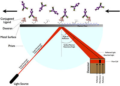 |
| The analyte molecules or biological objects are absorbed at the surface of metal. They cause the refractive index change in a thin layer on top of the metal. Due to the change of the refractive index, the angle of the plasmonic resonance is changed and detected. |
| Image from Wikipedia. See detailed explanation in Wikipedia here |
| See my page on the surface plasmons here |
Main idea: the detection of a small change of the refractive index due to bonding of a bio molecule to a metal.
![]() Operational principle:
Operational principle:
Step 1: A material, which can capture the biological molecule, is deposited on the surface of a metal.
Step 2: When the biological molecules are captured, the refractive index of a very thin layer on the top of the metal is changed.
Step 3: The resonance angle of a surface plasmon, which propagates on the top of the metal, is changed.
Step 4: The change of the resonance angle of the plasmonic resonance is detected by an optical method using a prism.
![]() I have proposed and demonstrated an effective method for reduction of the propagation loss of surface plasmon. The main idea is the insertion of a very thin dielectric layer of a different refractive index at the metal interface of a plasmonic waveguide. (Details see here). The reduction of propagation loss of the surface plasmon by this method is substantial. This method one of methods for the fabrication technology of a low-propagation-loss plasmonic waveguides for the integrated optical circuits (Details see here). Similar mechanism is used for the plasmonic sensor.
I have proposed and demonstrated an effective method for reduction of the propagation loss of surface plasmon. The main idea is the insertion of a very thin dielectric layer of a different refractive index at the metal interface of a plasmonic waveguide. (Details see here). The reduction of propagation loss of the surface plasmon by this method is substantial. This method one of methods for the fabrication technology of a low-propagation-loss plasmonic waveguides for the integrated optical circuits (Details see here). Similar mechanism is used for the plasmonic sensor.
![]() this sensor need to use an anti-body material in order to bond a substantial number of the analyte molecule to make change of refractive index (plasmonic resonance) detectable
this sensor need to use an anti-body material in order to bond a substantial number of the analyte molecule to make change of refractive index (plasmonic resonance) detectable
![]() Related Patents:
Related Patents:
US5313264A (1988). : Optical biosensor system. Claim: The first usage of a prism in plasmonic sensor
UUS5485277A (1994). Surface plasmon resonance sensor and methods for the utilization thereof. Claim: The first usage of plasmon resonance for sensing.
US20070065954A1 (2005).Surface plasmon resonance biosensor system for detection of antigens and method for determining the presence of antigens
![]() Demerits:
Demerits:
(1) The change of refractive index should be substantial due to the absorption of the bio-molecule.
(2) Difficulties with the precise control of the thickness uniformity of the absorbing layer. The plasmonic resonance significantly depends on the thickness of the absorbing layer, which variation generates substantial noise during detection other.
(3) Difficulties to make a small integrated detector, because it consists of a laser, a prism and a CCD camera, which all are bulk components.
(4) Difficulties of detection of a single molecule.
sensor 3(a). Bulk-property type Sensors using resonance optical reflection from multilayer dielectric structure
Detection of optical resonance in dielectric multilayer structure |
||||||
|
||||||
Fig.30. Detection of optical resonance in a CdMnTe multilayer. The refractive index of CdMnTe is higher for a higher Cd concentration. |
||||||
| Note: for sensoring function the substrate should be removed | ||||||
| click on image to enlarge it |
(differences (1) from plasmonic sensor): a dielectric multilayer (e.g. a Bragg mirror) with a thin metal layer is used instead of a 40-50 nm-thick noble metal film, thus providing a wide choice of working wavelength and sensing materials.
(differences (2) from plasmonic sensor): a resonance of the Bloch surface wave is used instead of the surface plasmon resonance.
(differences (3) from plasmonic sensor): better robustness and sensitivity because of a larger quality factor of the resonance (a narrower resonance peak)
Main idea: A multilayer dielectric structure (a 1D photonic crystal) is deposited on top of prism. There is an optical resonance in this multi layer structure (a resonance of (a 1D photonic crystal). As a result, there is a sharp peak in the wavelength reflection spectrum for a certain range of incident angles. When a biological object is approaching and bound with immobilized biomolecules, the peak position is changed since the peak position is extremely sensitive to degree of penetration of optical evanescent filed into the detected biological object.
Merit of optical-resonance sensor vs plasmonic sensor: High- Q resonance of the Bloch surface wave, wide selection of working wavelengths , a larger choice of used materials for the sensor.
sensor 4. Bulk-property type![]() Sensors using surface acoustic waves
Sensors using surface acoustic waves![]()
Main idea: (1) the detection of a small mass change on the surface of a detector due to bonding of bio molecules. (2) the detection of a small mass change on the elasticity of a thin layer on the surface of a detector due to bonding of bio molecules.
![]() Operational principle:
Operational principle:
Step 1: A material, which can capture the biological molecule, is deposited on the surface of an electro- acoustic film. .
Step 2: When the biological molecules are captured, the mass of a very thin layer on the top of the film is changed.
Step 3: The resonance frequency of a surface acoustic wave, which propagates on the top of the electro- acoustic film, is changed.
Step 4: resonance frequency of a surface acoustic wave is detected by a network analyzer.
![]() this sensor need to use an anti-body material in order to bond a substantial number of the analyte molecule to make change of the mass or elasticity of the top layer of the detector detectable
this sensor need to use an anti-body material in order to bond a substantial number of the analyte molecule to make change of the mass or elasticity of the top layer of the detector detectable
![]() Related Patents:
Related Patents:
Sensors utilizing a floating-gate transistor |
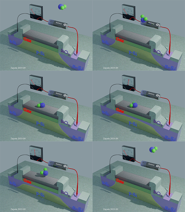 |
transistor consists of (1) two regions (emitter and collector) of n-Si, which conductivity is electron type; (2) n-Si (base), which conductivity is hole type; (3) the gate. |
| (analyte molecule is far for sensor): There is no current between collector and emitter, because of the high-resistivity Schottky barrier formed between n-Si and p-Si |
| (analyte molecule touches the gate metal): The electrical potential of the gate is changed and a thin region under the gate is formed, in which the conductivity becomes of the electron type. The current flows between the emitter and the collector and the presence of he analyte molecule is detected. |
| click on image to enlarge it |
US8134278B2 (2009). : Surface acoustic wave device and surface acoustic wave biosensor
JP2006313092A (2005). . Surface acoustic wave sensor and surface acoustic wave sensor system.
JP2008224582A (2007). .Gas sensor.
US20160313316A1 Surface acoustic wave sensor for influenza detection
![]() Demerits:
Demerits:
(1) The change of the elastic properties should be substantial due to absorption of the bio-molecules
(2) Difficulties to make a small integrated detector, because the sensor consists of a network analyzer and microwave components. Additionally, the size of the sensor and the detection area should be larger than the wavelength of the surface acoustic wave in order to get a reasonable sensitivity.
(3) Difficulties of detection of a single molecule.
Conductivity of biological objects |
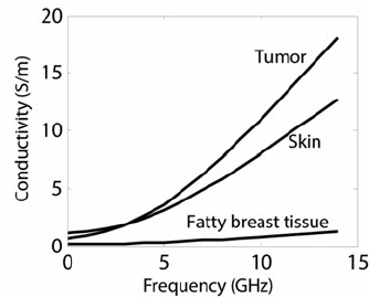 |
Fig. is from here |
sensor 5. charge-detection type  Sensors utilizing a floating-gate transistor
Main idea: the detected molecules change the charge and/or the Fermi level of the transistor gate. As a result, the transistor can switch the bias current on or off and detect the bio molecules
![]() Operational principle:
Operational principle:
Step 1: A detectable bio-molecule is bound to the transistor gate.
Step 2: The charge and/or the Fermi level of the gate is changed.
Step 3: The bias current of the transistor is changed and the molecule is detected.
![]() Related Patents:
Related Patents:
US4881109A (1986). Sensor using a field effect transistor and method of fabricating the same
EP1464953A1 (2003). .Biosensor comprising an organic field effect transistor and method for the fabrication of the sensor.
EP2366994A1 (2010). Biosensor on thin-film transistors
![]() Demerits:
Demerits:
(1) Large noise due to environment electrical field and charging
(2) Difficulties to use in a liquid due to the electrolyte charge. The ions in the electrolyte make a large noise.
(3) Difficulties of detection of a single molecule.
main problem ![]() of Sensors utilizing a floating-gate transistor
of Sensors utilizing a floating-gate transistor
Biological environment is an conductive electrolyte. The conductivity of biological environment is substantial (See here). It disturbs significantly operation of the sensor and creates a substantial noise.
sensor 6. electron microscope image SEM & TEM images
SEM images of biological objects |
||||||||||||
|
||||||||||||
SEM images are from here, here, here and here |
||||||||||||
| Click on image to enlarge it |
Main idea: the observation of biological objects in an scanning electron microscope (SEM) or transmission electron microscope (TEM)
![]() Operational principle:
Operational principle:
Step 1: The biological object is covered by a thin layer of metal
Step 2: The charge and/or the Fermi level of the gate is changed.
Step 3: The bias current of the transistor is changed and the molecule is detected.
![]() Demerits:
Demerits:
(1) It make images of a "frozen" biological world of the biological objects cover by a metal. There is no dynamic and life.
(2) The biological life exists only in a liquid environment. For the SEM and TEM observation that biological world is dried out. During the dry-out process the biological objects are alternated. The SEM and TEM make images of "mummies" of the biological objects.


![]()
(Main idea): A swarm of metallic particles are locally injected into the place of problem. Next, the particles are heated. As a result, the bacteria and virus is killed in one local place.
(navigation and positioning)  The swarm of particles can be navigated into exact required location by an external magnetic field. The exact position of particles relatively to body organs can be measured using conventional ultrasonic equipment, which is used be medical check. It should be mentioned that often this passive positioning is problematic for a small particles.
(heating)  The swarm of metallic particles is heated by an external source of microwave. Frequency of microwave should be ~ 1 GHz, when the microwave energy is still relatively high, but the penetration depth still reasonable ~ 1- 10 cm. (see here)
A. The mayor goal of the PMA is the recognition function of a molecule or a virus or a bacteria with the "Yes" or "No" output. It recognize a specific object by a specific features like shape, size etc.. A quantitative feature can also be recognized. E.g. a cancer cell can be recognized from a similar healthy cell by an amount of ami acid (or another specific elements) in its close environment. The PMA sensor can recognize a change of an amount of a specific element in environment.
A. The recognition function of the PMA sensor is of "YES/NO" type similar to the "Friend/Foe" function of an aviation radar. The PMA sensor gives a trigger signal when the specific object is touching the sensor surface and it induces the change of the PMA energy above a fixed level (threshold).
A. At one moment in time the PMA sensor either recognize or does not recognize the object currently touching its surface. It can recognize only one object. However, by real-time monitoring of the frequency, at which the specific object touches the sensor surface, the amount of the specific biological object in environment can be measured.
A. Even though a single PMA detector is able to recognize one biological object in one moment in time, an array of the PMA detectors may be used for "real-time" quantification
A The recognition of the PMA is of a trigger type. When the change of the PMA energy is above a threshold level, the recognition signal is triggered. Any smaller change is ignored. It is "YES/No" recognition. There are no intermediate states.
A. The PMA sensor should be designed so that only a specific biological object causes the largest change of the PMA energy and therefore gives the largest the detection signal. All another possible object in measured environment should give a smaller signal. E.g. the matched opening in the mask allows only an object of a specific shape and size to reach the detector surface and induce the largest change of the PMA energy. Any other object of a different shape or smaller size or larger size does fit to the mask opening, it causes significantly smaller change of the PMA energy and it is not recognized.
A. A change of orbital deformation due to the presence of an analyte molecule in the vicinity of the detector surface is the detection principle of the PMA sensor. The deformation should be just different when the specific biological object replaces water or another objects near the sensor surface. For any specific biological environment, the PMA sensor must be designed so that a change of the PMA energy is largest for a specific biological object, which should to be recognized.
A. The detection sensitivity of the PMA sensor is linearly proportional to the ratio of the touching area of an analyte molecule to the total area of the sensor. The smaller area of the detector is, the better the sensitivity of the PMA sensor is. Myself I have fabricated MTJ with diameter about 40-50 nm. For the MRAM application, several companies have demonstrated a MTJ with diameter smaller than 10 nm. Such small sensor can provide a sufficient sensitivity even for a small molecule.
A. The PMA effect is extremely sensitive to a tiny change to the material composition at its interface. As Oct. 2019, I have not tested the PMA sensor in a biological environment. However, I have tested the dependence of the PMA energy on a tiny change of material composition at interface. The change of the PMA energy is very large. E.g. there is an change of the anisotropy field (See here) of about 25% (~2 kGauss) for the change of amount of oxygen at a FeB interface less than 0.2%.
A. Another example of the very high sensitivity of the PMA effect to interface conditions is the VCMA effect. In the case of the VCMA effect, an applied gate voltage deforms slightly the orbitals at the interface of a ferromagnetic metal, which results in a substantial change of the PMA energy.
A. Another example is the VCMA effect in a sample, which has a gate with many defects. In this case, under a gate voltage the oxygen ions diffuse to or out of the metal interface, which causes a large VCMA effect (See here). In a solid (even with defects) the ion diffusion under an applied voltage is very weak . Even though the amount of diffused oxygen is very tiny (~0.1%), the change of the PMA energy is still very large.
A. In contrast to the plasmonic sensor,or sensor using surface acoustic waves, or magnetic- tag sensor, the PMA sensor does not need to use an adhesion material (like an antibody material). In contrast, any adhesion of analyte object or any other material to the detector surface should be avoided.
A. The plasmonic sensor, sensor using surface acoustic waves, are magnetic- tag sensor, they all need to accumulate some substantial amount of analyte objects (molecules) in order to detect it. All these detectors needs some change of the bulk properties of material in order to detect it and therefore they need some accumulation of amount of material. As a result,, these detection methods require some adhesion material (like an antibody material) on the detector surface in order to accumulate a sufficient amount of analyte objects (molecules). The detection principle of the PMA sensor is very opposite. It detects a touching event of an analyte object to the detector surface. The detection surface should not be blocked and any adhesion of any material to the detector surface should be avoided.
A. The challenge for the fabrication of the PMA sensor is very opposite. Any long-time adhesion of any molecules or other objects should be avoided. An undesired adhesion of any object to the sensor surface blocks an analyte object from reaching of the detector surface, therefore blocks the operation of the PMA sensor. This issue has some fundamental origin. The reduction of the PMA energy by an analyte molecule produces an attraction force, which may cause a substantial adhesion of the molecule to the sensor surface. It is an undesirable effect, which should be avoided.
A. The PMA sensor can detect more complex analytes such as bacteria or viruses or a biological cell. (See fingerprints of a biological object)
Each type of a virus has a very distinguish shape and size. Both methods of the molecular mask and the ordinary mask are well suitable for the virus detection.
A bacteria has lager size, which makes it easier to detect. However, many bacteria of different kind have near identical shape and size. Still bacteria detection using the ordinary mask might be an option for some application. Similarly, many biological cells of different kind have near identical shape and size. Still the method of the ordinary mask may be used to distinguished between two kind of cells of different size or shape.
The wall, membrane and capsule of a cell or a bacteria are very distinguish for each kind of bacteria or cell. When the cell or bacteria touches the PMA sensor, some features of its outside surface can be recognized and the bacteria or cell can be recognized. The features of the wall, membrane and capsule of a cell or a bacteria can be distinguish using an array of the PMA detectors (See here)
Another method to recognize a cell or a bacteria, the measurement chemical content (amount of specific amino acid or another element) in the close environment near the bacteria or the cell (See fingerprints of a biological object)
A. There are absolutely no similarities between the detection method of the magnetic tag and the method of the PMA sensor (maybe except that they both are made of a magnetic material). The PMA sensor detects an orbital deformation of its surface atoms by an analyte object. In contrary, the sensor of magnetic field detects the magnetic from magnetic tags, which are bounded to the analyte molecules. The PMA detector does not detect any magnetic field. The external magnetic field makes noise and disturbs the operation of the PMA sensor.
![]() The detection methods of PMA type and using a magnetic tag are two absolutely different detection methods having very different properties, abilities, purposes and problems!!!
The detection methods of PMA type and using a magnetic tag are two absolutely different detection methods having very different properties, abilities, purposes and problems!!!
![]() The known problems (See here) of the sensing using a magnetic tag have no any relation to the PMA sensor and have no influence on the performance of the PMA sensor.
The known problems (See here) of the sensing using a magnetic tag have no any relation to the PMA sensor and have no influence on the performance of the PMA sensor.
Khan et.al "Radio frequency controlled wireless drug delivery devices" Appl. Phys. Rev 2019.
![]()
![]() I am strongly against a fake and "highlight" research
I am strongly against a fake and "highlight" research ![]()
![]()
![]()
![]()
![]()
![]()
I will try to answer your questions as soon as possible