Dr. Vadym Zayets
v.zayets(at)gmail.com
My Research and Inventions
click here to see all content |

Dr. Vadym Zayetsv.zayets(at)gmail.com |
|
|
Spin -Photon memory
Injection of spin polarized electrons from semiconductor into nanomagnetFor the successful operation of the memory it is essential to inject photo-excited electrons form the semiconductor detector into the nanomagnet within short time interval less than 100 ps. The technology of fabrication of a semiconductor-nanomagnet contact with ultra low contact resistance is crucial for this purpose.
|
 |
 |
|
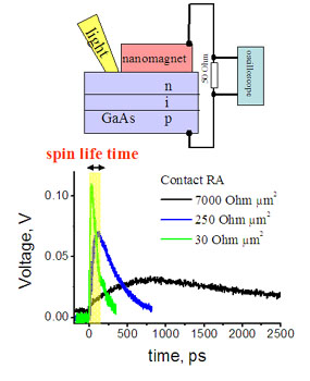
| Fig.3 Experimental measurements of electron injection time from p-i-n GaAs into Fe nanomagnet. Light excites the electrons in GaAs in close vicinity of the nanomagnet , which are injected into nanomagnet. The beam diameter is 4 um. Area of nanomagnet is 0.1 um2. Optical pulse width 170 fs. The yellow square shows the spin life time in GaAs | Fig.2 Equivalent circuit for the spin injection of photo-excited electrons p-i-n diode into nanomagnet |
The low resistance between n-GaAs and Fe can be achieved by inserting heavily-doped layer at the interface. Three identical samples with only different material of insertion layer were studied. The insertion layer was: a 30 nm of nn-GaAs in which the Si doping concentration is just near to the solubility limit (n=2 1019 cm-3) (Sample 1); a 10 nm of d-doped GaAs in which the Si doping concentration is over the solubility limit (n=2 1020 cm-3) (Sample 2); a 150 nm n-InGaAs graded layer followed by a 10 nm nn-InAs layer (Sample 3). The measured RA was 7000, 250 and 30 Ohm um2 for the Samples 1, 2 and 3, respectively. The time response of the p-i-n photo detectors was measured by sampling oscilloscope on a 50-Ohm load resistor connected between the nanomagnet and metallic contact to p-GaAs layer of the detector. The photocurrent was excited by 170-fs 10-pJ pulses at lambda=860 nm. Figure 3 shows the time evolution of photo-excited current. The injection time was 3 ns, 350 ps and 75 ps for the samples 1, 2 and 3, respectively. For the sample 3, the injection time is shorter than in spin life time in GaAs. Also, in the case of the Sample 3, the peak amplitude of injected current was significantly larger than in cases of Samples 1 and 2.
Therefore, the required short injection time below 100 ps has been achieved.
In this experiment I have used a nanomagnet with a little bit large area (1 um2) and low RA 30 Ohm um2. Since the contact area is larger, the contact resistance is small. Therefore, RC decay time becomes even smaller.
At first, the electron injection time was measured when the laser beam (diameter 4 um) was in vicinity of the nanomagnet (green line).Next, the laser beam was moved 6 um out of nanomagnet and the injection time was measured again. As can be seen from fig. 4, the injection time became 80-ps longer.
Next, I divided 6 um/80 ps= 75 um/ns. I was surprised to find that this number exactly is the value of the electron saturation velocity in GaAs. The electron saturation velocity is the maximum velocity, at which electrons can diffuse in a solid.
From this experiment it can be concluded that length of the detector in the spin photon memory should exceed about 6-7 um. Otherwise, even when a nanomagnet with lowest RA is used, it would be impossible to inject the spin from the semiconductor into the nanomagnet within the spin life time.
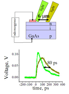 |
Fig.4 Influence of electron saturation velocity on electron injection time. |
Part 3. recording |
||||
|---|---|---|---|---|
|
I will try to answer your questions as soon as possible

 Video
Video 
