Dr. Vadym Zayets
v.zayets(at)gmail.com
My Research and Inventions
click here to see all content |

Dr. Vadym Zayetsv.zayets(at)gmail.com |
|
 |
IntroductionSi nanowire fabrication technology fiber/waveguide coupling setup integration: plasmonic + Si waveguides Out-plane plasmonic confinement AlGaAs waveguide (800 nm)in-plane confinement of plasmons
|
Modulation/switching of light at speed above limitation of material relaxation time
Technology(abstract:) The relaxation time is a major factor, which limits operation speed of the optical modulator.
Zayets 2022, July
|
| This |
The
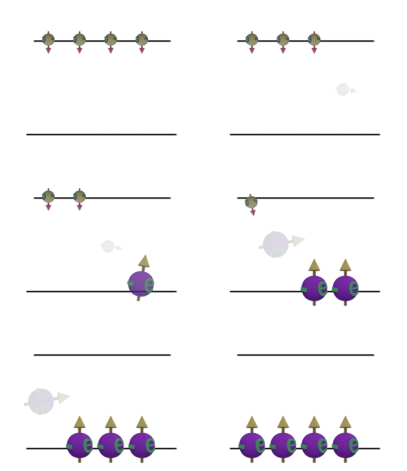
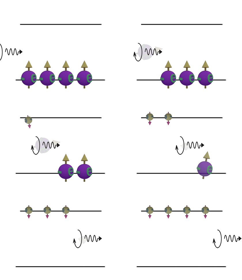
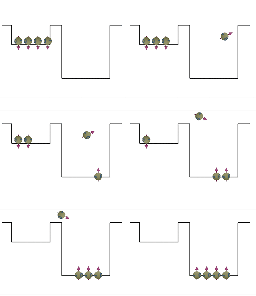
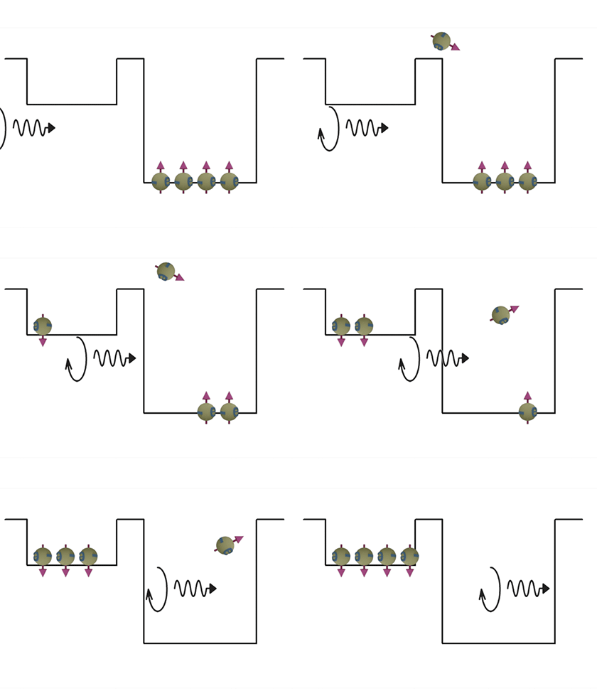
A. Ahe relaxation time is a major factor, which limits operation speed of the optical modulator. After the arrival of an electrical pulse, the modulator is switched to the “on” state” very quickly. After that there is a very long period until the “off” state of the modulator is reached again. This period is called the relaxation time. Since the next switching event can occur only after the initial state of the modulator is reached, the relaxation time is the major obstacle for an increase of the modulator speed.
| Interband transition. From up to down | Interband transition. From down to up. | |
|---|---|---|
| (Speed): Slow |
(Speed): Fast |
|
 |
 |
|
| Spontaneous emmision | Simulated emmision | |
| Intraband transition. From up to down | Interband transition. From down to up. | |
|---|---|---|
| (Speed): Moderate | (Speed): Fast |
|
 |
 |
|
| Spontaneous emmision | Simulated emmision | |
The simple differential phase modulator, which consists of two serially- connected phase modulators.
The RF generator provides a RF pulse to each modulator and there is a time delay between timings for the modulation pulse to reach the 1st and the 2nd modulators. Additionally, the polarity of the RF pulse is reversed. As a result, the phase shift, which is provided by each modulator, is exactly the same and the opposite polarity. Therefore, the total phase shift of the two modulators is exactly zero. As a result, the provided phase shift is proportional to the gradient of the modulation voltage, but not its absolute value.
From this simple math you can see that switching of the differential modulator is proportional to a product of the gradient of the change of the refractive index and the delay time. For example, for a conventional modulator the switching occurs when the phase change is equal to pi. In contrast, for a differential modulator the switching occurs when the product of gradient of the refractive index and the delay time is equal to pi.
Problem of the simple differential modulators:
There is a problem with this design, which is different relaxation time for the pulses of different polarities. When the modulation pulse is arrived, the refractive index rises in the 1st phase modulator , but forit decreases in the 2nd phase modulator . The problem is that these two processes, the increase and decrease of the refractive index, have different relaxation times and cannot fully balance each other.
This problem can be solved by this design, where one of the phase modulators is moved to another arm of the interferometer. It is not necessary to use a voltage inverter in this design. The rise of the effective index is used for both phase modulators. See Fig.11 below
This design is already good. However, it still might have a problem.
Problem of the symmetrical differential modulator:
The relaxation time depends on the defect density and other parameters, which may vary over different places of the wafer. As a result, two phase modulators fabricated at a different position may have a slightly different relaxation time and the exact balance might be a problem
This problem can be solved by this design, where one of the phase modulators is moved to another arm of the interferometer. It is not necessary to use a voltage inverter in this design. The rise of the effective index is used for both phase modulators. See Fig.12 and Fig.13 below
Problem of the Polarization- convertor-type differential modulator:
Still this design has a problem, because of the dependence of the relaxation time on the light polarization. It is because the contributions of the light and heavy holes for an electron transition are different for a TE and TM polarizations. As I explained before, it is because of a different symmetry of light and heavy holes.
| Symmtrical all- optical switch | ||||
|---|---|---|---|---|
|
||||
| Fig.21 Symmtrical differential amplitude modulator is made of a Mach- Zehnder interferometer, in whicha a phase modulator is installed in each arm. | ||||
| Both phase modulator provides the same phase shift. There is a delay line between between the modulators. Threfore, the RF signal reaches the modulators at a different time | ||||
| At a constant modulation signal, the phase shift are equal for both arms of the interferometer. As a result, the output amplitude is idependent of an absulute value of the modulation signal | ||||
| click on image to enlarge it |
| Polarization- convertor-type all- optical switch | ||||
|---|---|---|---|---|
|
||||
| Fig.22 | ||||
| click on image to enlarge it |
I will try to answer your questions as soon as possible