Dr. Vadym Zayets
v.zayets(at)gmail.com
My Research and Inventions
click here to see all content |

Dr. Vadym Zayetsv.zayets(at)gmail.com |
|
|
Measurements of Magnetic Circular Dichroism (MCD)
Magneto-optical measurementsThe3 methods of measurement of the Faraday rotation angle:1) with photo-elastic modulator (PEM)precession: poor 2) 2x2 switchprecession: high
Disturbing effect: Polarization rotation due to optical anisotropyThe polarization of light can be rotated in an anisotropic material. It is the disturbing and undesirable effect for the measurement
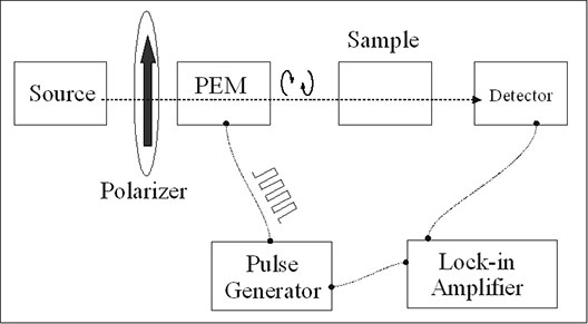
Measurement of MCD with photo-elastic modulator (PEM)Figures 1 and 2 show the conventional setup for measurements of magnetic circular dichroism (MCD). The photo-elastic modulator (PEM) makes the polarization of light modulated between left- and right- circular polarizations. The difference in absorption between left- and right- circularly polarized light is detected by the detector using the lock-in technique. Because of the use of a lock-in technique, this setup for MCD measurements has a high sensitivity. However, there is a high MCD signal only in the case when wavelength of light is close to material absorption edge. A transparent material has no any MCD response. This limits the amount of information about the sample, which could be obtained by the MCD measurements. Main merit of the conventional setup for measurements of MCD with PEM is the usage of the lock-in technique. It makes it significantly more sensitive than the conventional method of crossed polarizers for measurement of Faraday rotation angle. It is even more sensitive than the measurement setup with balanced detectors.
Measurement of MCD with a 2x2 optical switch
|
Setup for measurements of MCD with a 2x2 switch |
|
Fig.3 The setup for measurements of magnetic circular dichroism (MCD) using a 2x2 switch. The 2x2 switch is switching between two opposite directions of light propagation. The quarter wave plates QW1, QW2 and the polarizers P1,P2 makes light right circular polarized for both cases: (1) when light propagate from down to up (shown in red) and (2)
when light propagate from up to down (shown in green). The lock-in amplifier measures a small difference between absorption of the right-circular polarized light between two opposite directions of light propagations. Click on image to enlarge it.
|
In set-up with a 2x2 switch the optical absorption of right-circular polarized light ( or left circular polarized light ) for two opposite directions of light propagation.
Figure 4 shows the setup for measurements of the MCD using a 2x2 switch. It consists of an source of light, a light detector, a 2x2 optical switch, two polarizers and two quarter- wave plates, a pulse generator and a lock-in amplifier. The axes of the polarizers are in the same direction. The angle between the axes of the quarter-wave plates is 90 degrees. The axes of the polarizers are in the same direction. The angle between axes of the polarizers and the quarter-wave plates are 45 (-45) degrees.
The 2x2 switch is switching between two opposite directions of light propagation. The polarizer and quarter- wave plate make the light circular-polarized, when it pass through the sample. In both directions of light propagation, light is right circular polarized. Except the light propagation direction, nothing changes when 2x2 switcher is switched between its two states. Therefore, the output of the detector is only slightly modulated. The modulation amplitude is linearly proportional to the difference of the absorption of the circular- polarized light for two opposite directions (MCD). The MCD signal is detected with a high sensitivity and a high precision by the lock-in amplifier.
Transformation of polarization for setup of Fig.4 |
|
Fig.5 Evaluation of light polarization for measurement setup of Fig.4 for two opposite light propagation directions. The upper part is the phase diagram for the x- and y-component of polarization. The lower part shows the polarization vector as light propagates along the z-direction. In the forward direction the z-axis is directed from paper to viewer. In the backward direction the z-axis is directed from viewer to paper.
|
Setup for measurements of MCD with a 2x2 switch and polarization- maintaining fibers |
|
Fig.6 The setup for measurements of magnetic circular dichroism (MCD) using a 2x2 switch polarization- maintaining fibers. It is similar to the setup of Fig3, but instead of free-space polarizers the polarization- maintaining fibers are used
|
I will try to answer your questions as soon as possible