Dr. Vadym Zayets
v.zayets(at)gmail.com
My Research and Inventions
click here to see all content |

Dr. Vadym Zayetsv.zayets(at)gmail.com |
|
 |
Measurements of Kerr rotation angle
Magneto-optical measurementsThe3 methods of measurement of the Kerr rotation angle:1) Crossed- polarizersprecession: poor 2) Balance detectorprecession: moderate 2) 2x2 switchprecession: high
Disturbing effect: Polarization rotation due to optical anisotropyThe polarization of light can be rotated in an anisotropic material. It is the disturbing and undesirable effect for the measurement
Conventional setup: Crossed -polarizersFigures 1 shows the conventional setup for measurements of Kerr rotation angle using crossed polarizers. Polarized light is reflected from the sample and it is detected by the detector. In the front of the detector there is a polarizer P2, which axis is 90 degrees with respect to the axis of the polarizer P1. In the case when there is no polarization rotation, light is blocked by polarizer P2 and it can not reach the detector. When after the reflection the polarization is rotated, some light can reach the detector. Since the magnitude of the detected light is proportional to the rotation angle (the Kerr rotation angle), the rotation angle can be evaluated. Similar to the cross-polarizer setup for measurement of Faraday rotation angle, the demerit of this setup is a low sensitivity. The reason of the low sensitivity is the same. It is zero derivation of transmission when polarizers are crossed.
Setup with balanced detectorsFigures 2
Setup with 2x2 optical switch
|
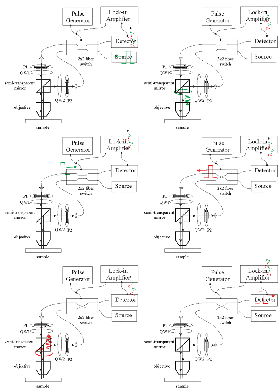
Fig.4. Setup for measurements of Kerr rotation angle using a 2x2 optical switch |
 |
| The setup for measurements of Kerr rotation angle. The 2x2 switch is switching between two opposite directions of light propagation. The quarter wave plates QW1, QW2 and the polarizers P1,P2 makes light right circular polarized. However, the polarization rotation is different for two switching states.(1) when switch is off, light is right circular polarized (shown in red) and (2) when switch is on, light is right circular polarized (shown in green). The lock-in amplifier measures a small difference between absorption of the right-circular polarized light between two opposite directions of light propagations. Click on image to enlarge it |
I will try to answer your questions as soon as possible