CdMnTe integrated optical isolator. The isolator for a monolithic integration
At present, there is a significant commercial demand for optical isolator and circulator, which could be integrated into photonic integrated circuit. We proposed to use (Cd,Mn)Te as a magneto-optical material for such isolator. The (Cd,Mn)Te exhibits a huge Faraday effect and can be grown on a semiconductor substrate. For (Cd,Mn)Te waveguide with (Cd,Zn)Te grown on GaAs substrate we achieved a high Faraday rotation of 2000 deg/cm, a high isolation ratio of 27 dB, a low optical loss of 0.5 dB/cm, and a high magneto-optical figure-of-merit of 2000 deg/dB/kG in a wide 25-nm wavelength range. These values are comparable or better to that of commercial discrete isolators.
Cd1-xMnxTe waveguide optical isolator
The conventional bulk-type optical isolator consists of a 45-degree Faraday rotator placed between two polarizers [Fig.1]. The angle between axes of entrance polarizer and exit polarizer is 45 degree degrees. In forward direction the polarization of light is 45 degree rotated by the Faraday rotator to be along the axis of the exit polarizer. Therefore, the light can pass through the isolator in forward direction. In backward direction, the direction of polarization rotation is opposite to that in forward direction due the non-reciprocal nature of the magneto-optical effect. At the entrance polarizer, the polarization is 90 degree to the polarizer axis and the light is fully blocked.
In present optical networks, ferrimagnetic garnet oxide crystals such as Y3Fe5O12 (YIG) and (GdBi)3Fe5Ob are used as magneto-optical materials for discrete optical isolators. Because most of the active optical elements (such as the laser diode, optical amplifier, modulator, and optical gate) are produced on GaAs or InP substrates, it is desirable to integrate monolithically all optical components on these types of substrate, but integration of the isolator is a difficult task. Waveguide optical isolator based on the garnet film has been reported (Ando et al.,1988). But the garnet-made isolators have not been monolithically integrated with semiconductor optoelectronic devices, because these oxide crystals can not be grown on semiconductor substrates.
Fig.1 Design of free-space optical isolator. The Faraday rotator is placed between entrance polarizer (left side) and exit polarizer (right side). Upper diagrams show polarization in forward direction. Lower diagrams show polarization in backward direction.
Paramagnetic semiconductor Cd1-xMnxTe is promising as a magneto-optical material for integrated optical isolators and circulators. Cd1-xMnxTe shares the zinc-blende crystal structure with the typical semiconductor optoelectronic materials such as GaAs and InP; thus its film can be grown directly on GaAs and InP substrates. Cd1-xMnxTe also exhibits a huge Faraday effect (its Verdet constant is typically 50-200 deg/cm/kG) near its absorption edge because of the anomalously strong exchange interaction between the sp-band electrons and the localized d-electrons of Mn2+. Furthermore, the tunability of its absorption edge from 1.56 to 2.1 eV with Mn concentration makes the Cd1-xMnxTe magneto-optical waveguide compatible with (Al,Ga,In)P:GaAs optoelectronic devices operating in the wavelength range of 600-800 nm. For longer-wavelength (λ=800-1600 nm) optoelectronic devices, Cd1-x-yMnxHgyTe can be used. Bulk optical isolators using these materials are now commercially available.
For the Cd1-xMnxTe to be used as a material for the waveguide isolator, several conditions should be satisfied. For a practical Cd1-xMnxTe waveguide isolator, the isolation ratio should exceed 20 dB, insertion loss should be below 1 dB and operation wavelength range should be wider than 20 nm. This performance can only be achieved with a magneto-optical waveguide having a mode conversion ratio above 95 % and a figure-of-merit above 100 deg/dB. Below we will show that using advanced waveguide structure and optimized fabrication technique, this conditions can be achieved in Cd1-xMnxTe waveguide grown on GaAs substrate.
Fig.3. TM-TE mode conversion ratio in Cd1-xMnxTe waveguide at λ=730 nm
The Cd1-xMnxTe has about 12% lattice mismatch with GaAs. The growth conditions of Cd1-xMnxTe on GaAs substrate should be well optimized. Otherwise, the high density of dislocation in Cd1-xMnxTe film causes high optical loss in Cd1-xMnxTe waveguide (Zaets et al.,1997) and low value of Faraday rotation. The Cd1-xMnxTe waveguide was grown by molecular beam epitaxy (MBE) on GaAs (001) substrate. We optimized the growth conditions and fabricated the Cd1-xMnxTe waveguide in the following way. In the beginning, GaAs substrate was thermally cleaned at 4000 C under atomic hydrogen flux to remove oxides from GaAs surface. Before initiating the growth, the GaAs substrate was kept for 30 minutes under Zn flux to prevent the formation of the undesired Ga2Te3 compound. At first, a thin 10 nm ZnTe film was grown on the GaAs substrate to initialize the (001) growth. Following a 1-µm thick CdTe buffer layer, Cd1-xMnxTe waveguide was grown. It consists of a 3-µm-thick Cd0.73Mn0.27Te waveguide cladding and a 1-µm-thick Cd0.77Mn0.23Te waveguide core. The waveguide core was sandwiched between two 500-nm-thick Cd1-xMnxTe (x=0.27-0.23) graded-refractive-index clad layers, for which the Mn concentration was changed linearly with thickness. We used the Cd0.73Mn0.27Te layer as a cladding layer, since GaAs is an optical absorber with a higher refractive index than that of Cd1-xMnxTe, a single Cd1-xMnxTe layer on GaAs does not work as a waveguide. One needs transparent cladding layers with smaller refractive index. Cd0.73Mn0.27Te satisfies these conditions because Cd1-xMnxTe with higher Mn concentration has a smaller refractive index and wider optical band gap. The graded-refractive-index clad layers are essential for Cd1-xMnxTe waveguide to achieve high magneto-optical TE-TM waveguide mode conversion and high optical isolation.
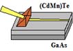
Fig.4. Structure of a (Cd,Mn)Te waveguide with (Cd,Mn)Te/(Cd,Zn)Te QW. The waveguiding light intensity distribution is shown in the right side .
Figure 2 illustrates the experimental setup for evaluating optical propagation loss and TE-TM waveguide mode conversion (Zaets&Ando,2000). A GaP prism was used to couple the laser light from tunable Ti:sapphire laser (λ=680 -800 nm) into a Cd1-xMnxTe waveguide. A cooled CCD TV-camera collected light scattered normally from the film surface. A linear polarizer was placed in front of the TV camera with its polarization axis perpendicular to the light propagation direction. With this configuration, only the TE mode component of waveguiding light can be detected by the high-sensitivity TV camera. In the absence of a magnetic field, a scattered light streak was seen when the TE mode was excited (Fig. 3(a)), but it was not seen when TM mode was excited (Fig. 3 (b)). Also, weak dot-like scattering on defects was seen in both cases.
For the evaluation of the magneto-optical TE-TM waveguide mode conversion, a magnetic field was applied in parallel to the light propagation direction. A light streak with a periodically modulated intensity was observed for both TE mode excitation (Fig. 3 (c)) and TM mode excitation (Fig. 3 (d)). Figures 3 (e)-(f) show the measured intensity of the modulated streak along the propagation length. The intensity was normalized to input intensity. The oscillations maxima in the case of TE excitation (Fig. 3 (e)) correspond to the oscillations minima in the case of TM excitation (Fig. 3 (f)) and vice versa. Under an applied magnetic field the polarization of the waveguide mode rotates because of Faraday effect. If the TE-TM mode phase mismatch is not zero, the eigenmodes of the waveguide are elliptically polarized and the rotation between TE and TM polarizations is not complete. As seen from Figs. 3 (c)- 3 (f), the Cd1-xMnxTe waveguide with the graded index cladding layer shows almost complete mode conversion.
Fig.5. Spatially modulated light streak from waveguide TE mode for CdMnTe waveguide with QW (a), (b) and waveguide without QW (c), (d) at λ = 760 nm (a), (c) and λ = 785 nm (b), (d) under magnetic field of 5.5 kG
The Cd1-xMnxTe waveguide with graded buffer layers has low optical loss, high TE-TM mode conversion efficiency (more than 98 %) and high isolation ratio (more than 20 dB). However, high isolation ratio was obtained in narrow about 3 nm wavelength range. For practical application of the isolator the operation wavelength range should be at least 20 nm. For the operation of the optical isolator, the rotational angle of Faraday rotator should be 450 (Fig.1) for any operational wavelength. Cd1-xMnxTe is a diluted magnetic semiconductor. It has a high value of Faraday rotation, but it is high only near its bandgap and near the bandgap the dispersion of Faraday rotation is significant as well. Of course, Cd1-xMnxTe is a paramagnetic material and at each wavelength the Faraday rotation can be tuned to 450 by the changing magnetic field. However, such tuning is not practical for real applications because a practical isolator needs a permanent magnet with a fixed magnetic field. Below we will show that it is possible to achieve practically dispersion-free Faraday rotation in wide wavelength range by combining in a waveguide Cd1-xMnxTe bulk material and a Cd1-xMnxTe quantum well (QW).
The Faraday effect in a Cd1-xMnxTe QW is greater than that of bulk Cd1-xMnxTe and it is not as dependent on wavelength. However, due to the two-dimensional nature of the QW, its optical properties become significantly different for light polarized in the plane of the QW and perpendicular to the QW. Therefore, for a waveguide composed of only a single QW, there is a big difference between propagation constants of TE and TM modes. Due to TE-TM mode phase mismatch, the linearly polarized light can be easily converted to elliptically polarized light, which reduces the performance of the isolator. Therefore, a waveguide composed of only a single QW cannot be used for the isolator application.
In order to make a high performance isolator, we need a large, wavelength independent Faraday effect and small phase mismatch between TE and TM modes. For that purpose, we proposed using an optical waveguide that combines Cd1-xMnxTe bulk material and a single QW (Debnath et.al. 2004)
Figure 4 shows the (Cd,Mn)Te/(Cd,Zn)Te QW waveguide structure. There are two buffer layers of ZnTe (10 nm) and CdTe (1 µm) and a Cd0.71Mn0.29Te (3 µm) waveguide clad layer. The waveguide core layer was sandwiched between two Cd1-xMnxTe (0.5 µm) graded layers in order to reduce TE-TM mode phase mismatch. The waveguide core consists of a Cd0.76 Mn0.2Te/Cd0.75Zn0.25 Te single QW and a 1-µm-thick Cd 0.75 Mn 0.25 Te layer, where thickness of the Cd0.76 Mn0.24Te well varies between 20–100 Å and the thickness of Cd0.75Zn0.25Te barrier is 100 Å.
Fig.6. Faraday rotation in Cd1-xMnxTe waveguide with QW and without QW
Figure 5 shows a spatially modulated light streak of the waveguide mode at two different wavelengths (760 and 785 nm) for the waveguides with QW and without QW. The high contrast between the minima and maxima of the light intensity oscillations shows that complete mode conversion is attained for both waveguides. The distance between peaks corresponds to 180 degrees of the rotation. For the waveguide without QW [Figs. 5 (c) and 5 (d)], there is a big difference of the rotational period for these two wavelengths. However, for the waveguide with QW [Figs. 5(a) and 5 (b)], there was no such difference. This means that, for the waveguide with QW, the Faraday rotation at these two wavelengths is the same. Also, for the waveguide with QW, the oscillation period is much shorter than that of the waveguide without QW. This corresponds to the larger Faraday rotation in the waveguide with QW.
Figure 6 compares the Faraday effect in Cd1-xMnxTe waveguide with QW and without QW at H=5.5 kG. In the case of the waveguide with QW, the Faraday rotation is very high (~1800 deg/cm) and it is almost constant in a wide wavelength range. Figure 7 shows the wavelength range within which more than 95% conversion efficiency was obtained for the waveguide with single QW as a function of well width. For well widths of 20–40 Å, the operational wavelength range is as wide as 25-nm. However, for thicker well widths of 70–100 Å, the operational wavelength range sharply decreases. Analysis shows that the expansion of the wavelength range for thinner QW waveguides was due to the reduction of the mode phase mismatch, to as low as 50 deg/cm, whereas this value rose to more than 500 deg/cm for thicker QW waveguides. Thinner QW waveguides have high Faraday rotation (≈ 2000 deg/cm) and small phase mismatch (≈ 50 deg/cm) This is the reason why thinner QW waveguides provided a wider operational wavelength range of complete mode conversion. From this result we conclude that, for the practical optical isolator application, only waveguides with a single QW thinner than 40 Å can be used.
Fig.7. Wavelength range, within which the complete mode conversion is obtained, as a function of QW width. Inset shows the isolation ratio.
For an integrated optical isolator, the CdMnTe magneto-optical waveguide has to be integrated with a reciprocal polarization rotator and a polarizing beam splitter. Both these components can be fabricated utilizing passive optical waveguides. The material of the waveguides is not essential for the operation of these components. Therefore, it is better to use the same passive waveguides as utilized for optical interconnection in a photonic circuit, where the isolator should be integrated. Figure 8 shows an example of a waveguide-type reciprocal polarization rotator. It is a passive optical waveguide in which the top is cut at an angle of 45 degrees. TM and TE modes are not eigenmodes in this waveguide. Therefore, there is a conversion between TM and TE mode along mode propagation. The length of this waveguide can be adjusted to achieve the desirable polarization rotation. The waveguide type reciprocal polarization rotators were demonstrated utilizing Si waveguide (Brooks et al., 2006], AlGaAs waveguides (Huang et al., 2000) and GaInAsP/InP waveguides (Kim et al.,2009). Figure 11 shows an example of a waveguide-type polarizing beam splitter. It is a 2x2 waveguide splitter. In any waveguide splitter, the coupling between an input port and an output port depends on the mode propagation constant. Generally, in an optical waveguide the propagation constants of TM and TE modes are different. Therefore, it is possible to adjust the splitter so that the TM mode couples from port 1 into port 4 and the TE mode couples from port 1 into port 3. The waveguide-type polarizing beam splitters were demonstrated utilizing Si waveguide (Fukuda et al., 2006) and InGaAsP–InP waveguides (Augustin et al.,2007).
Figure 10 shows the design of a waveguide-type polarization-independent optical isolator. It consists of two polarizing beam splitters connected by two arms. Each arm consists of an 45-degree reciprocal rotator and a 45-degree Cd1-xMnxTe -made Faraday rotator. There is an optical absorber at port 2 to absorb backward travelling light. In the forward direction, the direction of polarization rotation in the Faraday rotator is the same as that in the reciprocal rotator and the total rotation angle by the reciprocal rotator and the Faraday rotator is 90 degrees. The light of both polarizations propagates through the isolator from input 1 port to output port 3. In the backward direction, the direction of polarization rotation in the Faraday rotator is opposite to that in the reciprocal rotator due to the non-reciprocal nature of the Faraday rotator. In this case, the total rotation angle is zero. The light propagates from output port 3 to the port 2, where there is an absorber. Therefore, the input port 1 is isolated. The optical paths for each polarization are shown in Fig. 10. A waveguide-type polarization-independent optical circulator can be fabricated utilizing the same design. In this case the correspondence between the input and output ports is: port 1-> port 3, port 2 –>port 4, port 3 -> port 2, port 4 -> port 1.
In conclusion, the high performance of Cd1-xMnxTe waveguide isolator grown on GaAs substrate was demonstrated. Complete TE-TM mode conversion, a high Faraday rotation of 2000 deg/cm, a high isolation ratio of 27 dB, a low optical loss of 0.5 dB/cm, and a high magneto-optical figure-of-merit of 2000 deg/dB/kG were achieved in a wide 25-nm wavelength range. These values are comparable or better to that of commercial discrete isolators. The propagation of waveguide mode in Cd1-xMnxTe waveguide is very similar to the light propagation in magneto-optical bulk media. Therefore, non-reciprocal elements such as an optical isolator, circulator and polarization independent isolator can be fabricated by Cd1-xMnxTe waveguides using a similar scheme as is used for free space components. Therefore, using Cd1-xMnxTe all these components can be integrated with semiconductors optoelectronical components.
Fig.10. Polarization-independent waveguide-type optical isolator / circulator. Polarization transformations for both propagation directions are shown.
K. Ando; T. Okoshi, and N. Koshizuka, (1988) "Waveguide magneto-optic isolator fabricated by laser annealing," Applied Physics Letters, Vol. 53, 4-6 ,1988.
L.M. Augustin; R. Hanfoug, R.; J.J.G.J van der Tol,.; W.J.M de Laat & M.K Smit (2007) "A Compact Integrated Polarization Splitter/Converter in InGaAsP–InP", IEEE Photonics Technology Letters , Vol. 19, No. 17, 1286 – 1288, Sept. 2007 .
C. Brooks,P.E. Jessop, H. Deng , D.O. Yevick, G. Tarr (2006), "Passive silicon-on-insulator polarization-rotating waveguides ", Optical Engineering Vol. 45, No. 4, 044603, 2006.
M. C. Debnath; V. Zayets & K. Ando, (2007). "(Cd,Mn)Te/(Cd,Zn)Te quantum-well waveguide optical isolator with wide wavelength operational bandwidth" Applied Physics Letters, vol. 91, No.4, 043502 , July 2007.
H. Fukuda; K.Yamada,; T. Tsuchizawa; T. Watanabe;,H. Shinojima & S. Itabashi (2006) "Ultrasmall polarization splitter based on silicon wire waveguides" Optics Express Vol. 14, No. 25, 12401, Dec. 2006.
J. K. Furdyna (1988), "Diluted Magnetic Semiconductors," Journal of Appled Physics vol. 64, R29- R64, 1988.
J.Z. Huang, R. Scarmozzino, G. Nagy, M.J. Steel, R.M. Osgood (2000), "Realization of a compact and single-mode optical passive polarization converter ", IEEE Photonics Technology Letters, Vol. 12, No. 3, 317-319 , Mar 2000
S.H. Kim, R. Takei, Y. Shoji & T. Mizumoto (2009) "Single-trench waveguide TE-TM mode converter ", OPTICS EXPRESS vol. 17, No. 14, 11267-11273. Jul.2009.
K. Onodera; T. Masumoto & M. Kimura (1994)" 980 nm compact optical isolators using Cd/sub 1-x-y/Mn/sub x/Hg/sub y/Te single crystals for high power pumping laser diodes," Electronics Letters Vol. 30, 1954- 1955, 1994.
H. Yokoi; T. Mizumoto; T. Takano & N. Shinjo (1999), "Demonstration of an optical isolator by use of a nonreciprocal phase shift," Applied Optics vol.38, 7409-7413, 1999.
W. Zaets; K. Watanabe & K. Ando (1997) "CdMnTe magneto-optical waveguide integrated on GaAs substrate," Applied Physics Letters, vol. 70, No. 19, 2508-2510, Mar. 1997.
W. Zaets & K. Ando (2000), "Magneto-optical mode conversion in Cd1-xMnxTe waveguide on GaAs substrate," Applied Physics Letters, vol. 77, No. 11, 1593- 1595, Sep. 2000.
V. Zayets; M. C. Debnath & K. Ando (2004), "Complete magneto-optical waveguide mode conversion in Cd 1-xMnxTe waveguide on GaAs substrate," Applied Physics Letters, vol. 84, No. 4, 565- 567, Jan. 2004.
I truly appreciate your comments, feedbacks and questions
I will try to answer your questions as soon as possible